
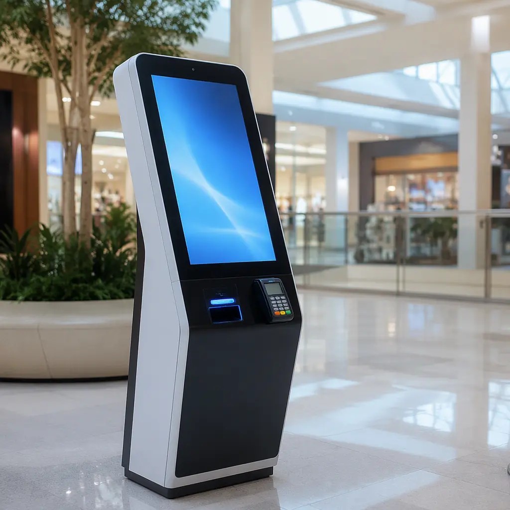
A self-service kiosk is a computer bolted to the floor of a shopping mall, a gas station forecourt, or a train station. Running continuously, touched by strangers, and nobody is there when it fails. A vending machine is the same story with motors and refrigeration added. The electronics inside operate in an environment that combines consumer temperatures with industrial duty cycles: 24/7 operation, wide ambient swings, power quality from commercial mains, and years of unattended service between maintenance visits.
This guide covers the PCB architecture, the design requirements, and the manufacturing and testing decisions that keep kiosk and vending electronics alive in the field, written from the perspective of the factories that build these boards at volume. We assemble kiosk and payment boards at Huaxing PCBA across 8 SMT lines, and the reliability requirements below are the ones our customers' products actually ship with. For the payment side of the architecture, our POS terminal PCB guide goes deeper into EMV and tamper requirements.
The Kiosk Electronics Architecture
A kiosk is not one board. It is a small system of boards and modules, each with different reliability demands. Understanding the architecture is the first step to specifying it correctly.
| Module | Function | Key PCB Requirements |
|---|---|---|
| Main computer board | OS, application, network | SoM or industrial SBC, high-speed routing, long-life components |
| Display driver board | Touchscreen, LVDS/eDP output | Differential pair routing, ESD on touch lines |
| Payment board | Card reader, NFC, QR, cash | EMV security, tamper mesh, secure element |
| Peripheral control board | Vend motors, lock solenoids, sensors | High-current drivers, flyback protection, opto-isolation |
| Power distribution | AC-DC to board voltages | Creepage/clearance, surge protection, hold-up |
| IoT/telemetry board | Remote monitoring, OTA, inventory | Cellular/LTE-M, antenna design, low-power standby |
Most kiosk OEMs do not design all of these in-house. The main computer is often a commercial off-the-shelf SoM, the SoM carrier board guide covers the connector, power tree and high-speed routing that carrier board demands. The boards the OEM does design, payment, peripheral control, power, are where the reliability requirements concentrate.
Key Takeaway: Specify the architecture first: which boards you design, which are COTS modules, and where the interface boundaries sit. The reliability budget must be allocated before layout starts. The peripheral and power boards are where kiosk field failures actually happen.
Always-On Power and Thermal: The Two Killers
Kiosk boards fail from heat and power quality before anything else. A board that runs continuously in a sealed enclosure with a touchscreen and a payment reader behind it lives at 50-70°C internally, in a cabinet that may also house a refrigerator compressor (vending) or direct sun (outdoor kiosks).
Design for continuous, not burst, operation
Consumer electronics are rated for burst use, a few hours a day. A kiosk board runs 8,760 hours a year. That changes component derating: electrolytic capacitors near heat sources need 105°C ratings with derated lifetime, high-current traces need wider copper than burst-use suggests, and the processor needs a thermal solution sized for worst-case ambient, not typical ambient. The thermal management guide covers heat sink and thermal via design for continuous loads.
Power quality: surges, dips and hold-up
Kiosks plug into commercial mains with refrigerators and HVAC on the same circuit. Specify surge protection (MOV plus TVS on the input), a power supply with 10ms+ hold-up time, and undervoltage protection that makes the system reboot cleanly instead of hanging. The high-voltage PCB design guide covers the creepage and clearance rules for the mains-side section.
Fanless cooling favors spread-out layout
Kiosk boards usually run fanless (fans fail, collect dust, and nobody cleans them). That means thermal management is done in layout: power components spread rather than clustered, thermal vias under hot parts, and board area used as a heat spreader. A 4-layer board with solid ground and power planes conducts heat dramatically better than a 2-layer board, specify the layer count with thermal conduction in mind.
Payment Security: EMV, Tamper and Certification
If the kiosk takes payments, the payment board carries obligations that go beyond engineering, they are contractual and regulatory. The POS terminal guide covers EMVCo and PCI requirements in detail; the essentials for the PCB itself are these:
Tamper mesh and secure element on the board
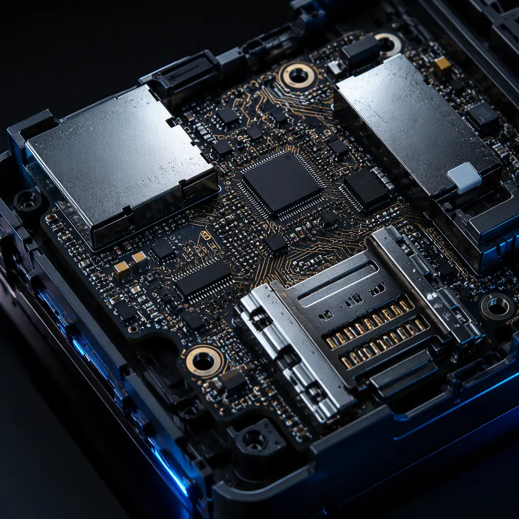
Card data must be protected at the hardware level: a tamper mesh around the card-reader section, a secure element storing keys, and tamper detection that erases keys when the enclosure is opened. The mesh is a fine-grid PCB layer pattern. Its layout, via pattern and detection circuitry are part of the board design, not an add-on module. The hardware security design guide covers tamper mesh implementation.
EMVCo and PCI PTS certification constrain the design
Certification comes after the design is frozen, and it fails on layout details: trace spacing that lets card data leak to adjacent nets, missing shielding around the card interface, inadequate ESD protection on the reader connector. Involve the certification house during layout, not after. Retrofitting shielding and mesh after a failed evaluation costs more than a second prototype.
Contactless and QR: antenna and interface layout
Contactless payment adds an NFC antenna, either a PCB antenna on the board edge or a separate FPC. PCB antennas need clearance zones and impedance-matched feed lines; the antenna design guide and NFC antenna guide cover tuning and matching for exactly this application.
Touch, Display and Connectivity
The user-facing half of the kiosk, touchscreen, display, and network, has its own set of rules, mostly about signal integrity and ESD.
Display routing: differential pairs, shielded from noise
LVDS or eDP links to the display panel are high-speed differential pairs that must be length-matched and kept away from the power and motor-drive sections of the board. The display driver board guide covers LVDS/eDP routing rules, and the HMI design guide covers the touch panel interface side.
ESD on every user-facing line
Touch lines, USB ports, the card reader connector, and the headphone jack if present: every path from the outside world to the board needs ESD protection. Kiosk ESD events are frequent (dry climates, synthetic clothing, 24/7 public use) and the damage is often latent: a slightly degraded touch controller that fails after six months. The ESD control guide covers protection device selection and placement.
Connectivity: cellular for the ones in the field
Vending machines and outdoor kiosks are rarely on wired Ethernet. The telemetry board needs cellular (LTE-M or Cat-1) with a properly designed antenna, the cellular IoT module guide covers antenna integration, and the GNSS guide applies if the kiosk reports location.
Motors, Solenoids and the High-Current Side
The vending-specific half of the system, vend motors, lock solenoids, refrigeration control, is where boards die from a different cause: switching inductive loads.
Flyback protection is not optional
Every relay, solenoid or motor driver must have a flyback diode or TVS across the inductive load. Without it, the switching transient kills the driver, the MCU, or both, the classic "the board worked in the lab and died in the machine" failure. The SMPS layout guide covers the switching-node layout discipline that applies here too.
High-current traces sized for stall current, not running current
A vend motor's running current is small; its stall current can be 3-5x higher when a product jams. Size the copper for stall current with margin, add current sensing per motor channel, and design the firmware to cut power on stall. The trace width guide has the IPC-2152 math for copper sizing.
Isolate the motor side from the logic side
Motor transients and ground bounce must not reach the main board. Use opto-isolation or separate ground planes between the peripheral control board and the main computer, and route the motor harness away from signal lines. The industrial control PCB guide shows the isolation and grounding patterns used in PLC-grade designs.
Manufacturing and Testing for 24/7 Reliability
The design rules only pay off if the manufacturing and test program matches the duty cycle. These are the requirements we build kiosk and vending boards to:
Conformal coating for the environments you cannot control
Indoor kiosks still see humidity, condensation and dust; outdoor and vending units see much worse. Specify conformal coating (acrylic or polyurethane) on the peripheral and power boards, with connector areas masked. The conformal coating guide covers material selection and the IPC-CC-830 acceptance criteria.
Burn-in catches the infant mortality
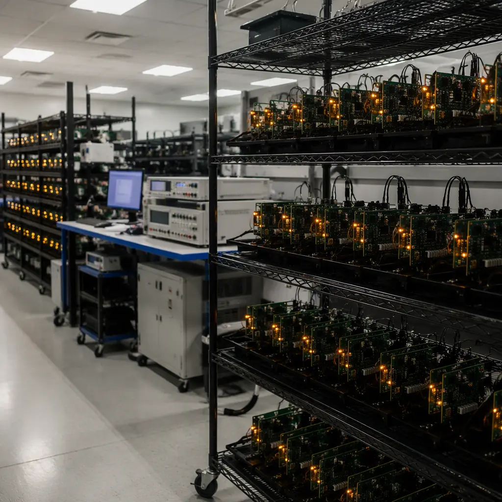
Kiosk boards are exactly the application where a 48-72 hour burn-in at elevated temperature pays for itself: the boards that fail in the first week of field service fail in burn-in instead, when they cost 1/100th as much to replace. The burn-in and ESS guide covers how to size the window and temperature for an always-on product.
100% electrical test plus functional test of the system
ICT or flying probe catches assembly faults; the functional test, booting the board, driving the display, cycling the vend motors, catches integration faults. For kiosk boards, the functional test is where the value is: a board that passes electrical test but fails to boot is a board you cannot ship. The test method guide maps the right test to your volume.
Long-life component sourcing and traceability
Kiosk products have 5-10 year life cycles. Specify long-life components (industrial temperature grades, 10-year availability parts), and require lot traceability so a field failure can be traced to a component batch. The obsolescence management guide and the traceability guide cover both programs.
Specifying Your Kiosk Board Program
A kiosk or vending PCB program succeeds on specification discipline: the architecture defined up front, the thermal and power budgets allocated to each board, the payment security requirements locked before layout, and the test program matched to 24/7 duty. Work backward from the field environment, ambient temperature range, power quality, payment certification, expected service interval, and every design and manufacturing decision follows. The PCB specification guide shows how to write the RFQ document, and the box-build guide covers the step from boards to finished kiosks.
Huaxing PCBA manufactures kiosk and vending electronics under IPC Class 2 and Class 3 programs, with conformal coating lines, 48-72 hour burn-in racks, and functional test fixtures built for your board, plus long-life component sourcing across 8 SMT lines. Read our payment terminal guide for the security requirements, or send your design for a DFM review and a manufacturing quote within 24 hours.
