
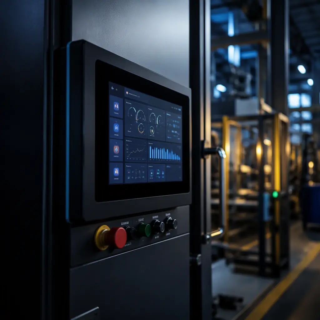
Human-machine interface (HMI) panels sit on every CNC machine, packaging line, and building automation controller: a 4.3–15 inch display with touch input, a processor board behind it, and field-bus connectivity to the machine. Unlike consumer tablets, an industrial HMI is a 10-year product. It runs continuously at elevated ambient temperature, gets subjected to 8 kV ESD events from operators and 1 kV surges from the field wiring, and must keep its touch and display working through all of it. Every one of those requirements lands on the PCB.
This guide walks through the five subsystems that make or break an HMI board: the processor/display architecture, display interface routing, projected capacitive touch, isolated industrial power, and the EMC/ESD immunity chain. It closes with the manufacturing and testing steps that keep a 10-year design alive. Huaxing PCBA builds HMI and industrial control electronics across 8 SMT lines, the same rules apply to our industrial control boards and display driver boards.
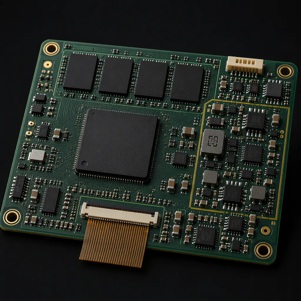
HMI Board Architecture: What Actually Sits Behind the Panel
A typical industrial HMI board carries a Cortex-A class application processor (or a high-end MCU with a graphics LCD controller), DDR memory, eMMC or SD storage, a display connector, a touch controller, isolated DC-DC power, and field-bus interfaces. Ethernet, RS-485, CAN or USB. The layout problem is that a 1 GHz processor with DDR3/DDR4 signaling sits centimeters from a switching power supply and a touch sensor that must resolve a few picofarads of capacitance change.
Choose the display interface before the stackup
The panel interface (RGB parallel, LVDS, MIPI-DSI or HDMI) dictates the number of layers and the routing rules. A 24-bit RGB interface at 60 Hz needs 28+ traces on the board and drives the stackup toward 6 layers; MIPI-DSI or LVDS compresses the same data onto 2-4 differential pairs. The display driver board guide compares the interface options in detail.
Keep the processor power tree clean
An application processor needs multiple rails (core, I/O, DRAM, analog) sequenced at power-up. Each rail needs its own bulk capacitance near the regulator and local decoupling at the BGA; the switching regulators should sit on the opposite side of the board from the display connector and touch traces. The power integrity guide covers rail planning for processor boards.
Plan for 10-year component availability
Industrial HMIs ship for a decade, so the BOM should favor long-lifecycle parts. And the layout should allow a second-source footprint for the processor, DRAM and touch controller. Our component obsolescence guide covers last-time-buy planning and footprint-compatible alternates for exactly this class of product.
Key Takeaway: The display interface choice is a board-level decision made first, it sets the layer count, the routing rules and the connector budget for the whole HMI.
Display Interface Routing: LVDS, MIPI-DSI and RGB
Display signals are the fastest traffic on an HMI board and the most sensitive to layout. The table below summarizes the four interfaces you will meet in practice:
| Interface | Signals | Data Rate | Max Cable | Typical Use |
|---|---|---|---|---|
| RGB parallel | 18-24 bit + clock | ~65 MHz clock | <10 cm | Small TFT panels, low cost |
| LVDS | 4 diff pairs + clock | ~85-135 MHz/pair | 1-5 m | 7-15" industrial panels |
| MIPI-DSI | 1-4 diff lanes + clock | ~500-1500 Mbps/lane | <30 cm | Smart displays, small panels |
| HDMI | 3 TMDS pairs + DDC | Up to 3.4 Gbps/pair | 5-15 m | External monitors, large panels |
Impedance and length matching for differential pairs
LVDS and MIPI-DSI pairs need controlled impedance, 100 Ω differential for LVDS, 100 Ω for MIPI DSI, with intra-pair skew under 5 ps (roughly 0.8 mm of trace). Keep the pairs on a solid reference plane, avoid vias in the pair if possible, and never route them under the switching regulators. The signal integrity guide has the via and reference-plane rules.
RGB parallel: group the bus and guard the clock
For an RGB panel, route the data bus as a group with matched length (typically within 1-2 mm), keep the pixel clock short and flanked by ground, and add series resistors (22-33 Ω) near the processor to damp ringing. EMI from a 24-bit RGB bus is a classic radiated-emissions failure, the EMC compliance guide covers the filtering and shielding fixes.
Connector placement and cable shielding
The display connector should sit on the board edge nearest the panel, with the FFC/FPC cable kept as short as practical and shielded if it crosses the power section. Ground the cable shield at the board end only to avoid a ground loop with the panel chassis.
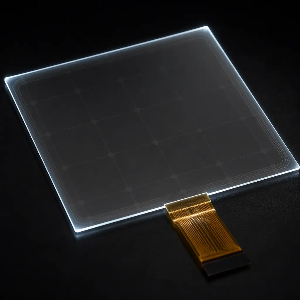
Projected Capacitive Touch: Noise Immunity Is the Design
Most industrial HMIs today use projected capacitive (PCAP) touch, which works through glass and gloved fingertips. The touch controller measures capacitance changes of 0.1–1 pF on an ITO sensor grid. Which makes it uniquely vulnerable to the noise the rest of the board generates.
Separate the touch sensor from display and power noise
The sensor FPC must not run parallel to the display cable or the backlight inverter wiring. The touch controller's I²C or USB traces should be short, and the controller should have its own quiet ground island referenced to the board at one point. Display refresh noise couples into the sensor through the shared glass, many controllers use a synchronization input from the display timing to sample between refresh bursts.
ESD path for the touch surface
The touch glass is a direct ESD entry point: 8 kV contact discharges hit the sensor edge and travel down the FPC into the controller. Every HMI needs a TVS array on the touch I²C/USB lines at the connector, a low-impedance chassis-ground path from the glass bezel, and a spark gap or discharge resistor to ground on the sensor's unused electrodes. The ESD control guide details the protection topology.
Resistive touch for the harshest environments
Where operators wear heavy gloves or the panel sees conductive dust, resistive touch (analog 4-wire) is still the reliable choice. It needs an ADC with a clean analog reference and short routed wires to the sensor; the trade-off is lower durability and no multi-touch, but the board design is far simpler.
Power and Isolation: 24 V In, Clean Rails Out
Industrial HMIs are powered from a 24 V DC machine supply (nominal range 9-36 V), often shared with motors, solenoids and contactors on the same bus. The board's power section has to survive what arrives on that bus, and keep the processor side clean.
Galvanic isolation between field power and logic
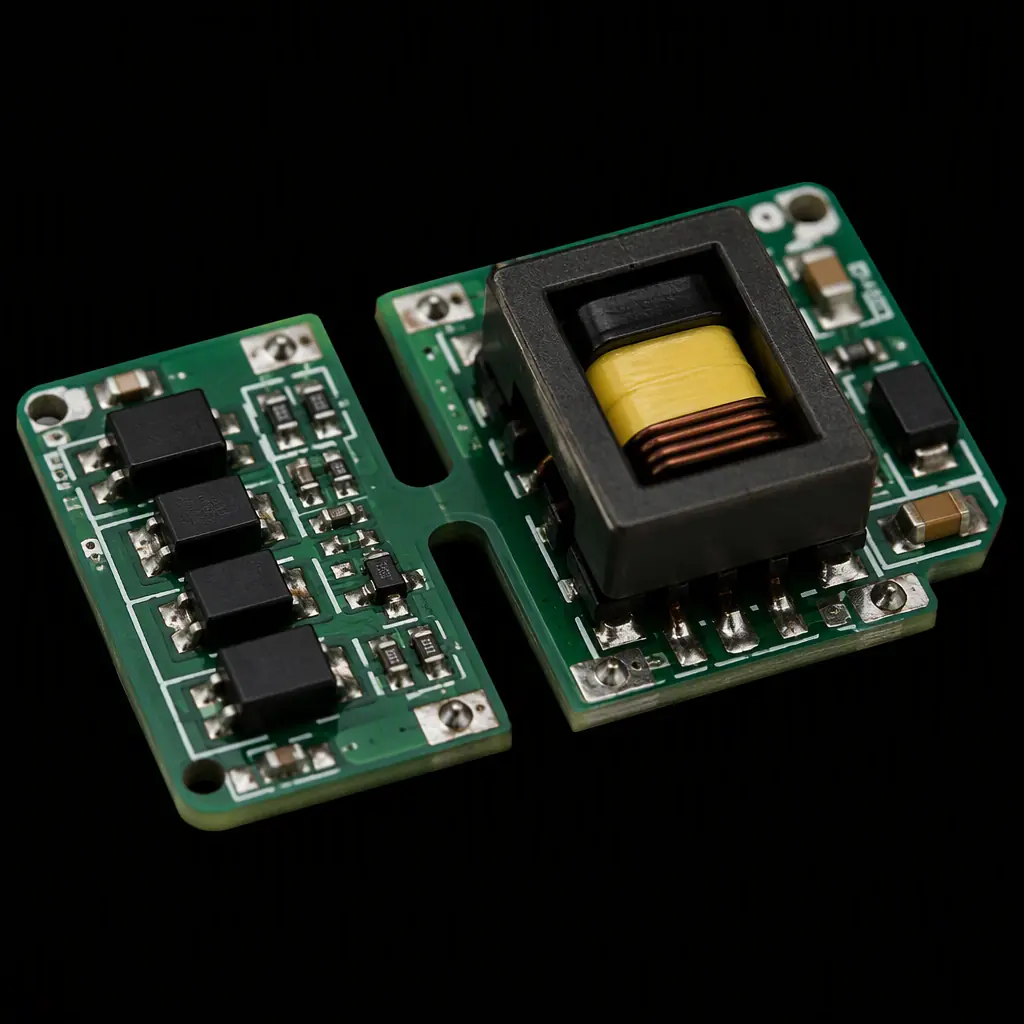
Isolated DC-DC converters (typically 1.5-3 kV isolation per EN 61010 / IEC 61558) separate the 24 V field side from the logic side, so a fault on the machine bus cannot reach the processor. The isolation barrier needs a clean slot in the PCB, ≥6 mm creepage across the barrier at 250 V working voltage, and the converter's ground plane must not bridge the slot. The high-voltage PCB guide covers slot and creepage layout.
Input protection: reverse polarity, surge and transients
The 24 V input needs a reverse-polarity protection FET or diode, a TVS for IEC 61000-4-5 surge (1 kV line-to-line, 2 kV line-to-ground for industrial), an input fuse, and bulk capacitance sized for the DC-DC inrush. The EMC guide's input-filter section shows the component ordering that actually passes the test.
Thermal derating for sealed enclosures
An HMI panel is often sealed (IP65) with no fan, so every watt the board dissipates heats the panel interior. The DC-DC converter and backlight driver dominate the thermal budget; the layout must spread their heat through copper pours and vias to the board edges, where the panel chassis conducts it out. The thermal management guide has the via-array and copper-spreading rules for sealed enclosures.
The Immunity Chain: ESD, EFT, Surge and Radiated Fields
An HMI on a factory floor is tested against IEC 61000-4-2 (ESD), 61000-4-4 (EFT/burst), 61000-4-5 (surge) and 61000-4-3 (radiated immunity up to 10 V/m). These are PCB-level problems before they are enclosure problems.
| Standard | Typical Industrial Level | Primary PCB Defense |
|---|---|---|
| IEC 61000-4-2 ESD | 8 kV contact / 15 kV air | TVS at all external connectors, chassis ground path |
| IEC 61000-4-4 EFT | 2 kV on I/O lines | Common-mode chokes, ferrite beads, filtering caps |
| IEC 61000-4-5 Surge | 1-2 kV on power | MOV/TVS + series impedance, gas tube for field wiring |
| IEC 61000-4-3 Radiated | 10 V/m, 80 MHz-6 GHz | Shielded enclosure, filtered I/O, solid ground planes |
Treat every external connector as an attack surface
Ethernet (magnetics + TVS), RS-485 (TVS to ground on both lines), CAN (TVS + common-mode choke), USB (TVS + ferrite): every wire that leaves the panel needs protection at the connector, before the transceiver. The RS-485/RS-232 design guide shows the transceiver protection topology for long field runs.
Ground strategy: chassis ground vs logic ground
The panel chassis must be the sink for all ESD and surge currents, with a separate chassis ground plane (or star point) that ties to logic ground only at the power entry. Connector shields, TVS grounds and the DC-DC's isolated side all reference chassis ground. Getting this single-point discipline wrong turns every ESD test into a logic reset.
Pre-compliance test with the real panel
An HMI board passes ESD differently mounted in its metal bezel than on a bench. Pre-compliance testing should use the production enclosure, with the touch glass installed, before the formal test house visit. The testing methods guide covers how to set up meaningful pre-compliance passes.
Manufacturing and Test for 10-Year HMI Boards
Industrial HMI boards are assembled and tested differently from consumer boards because the failure cost is a stopped production line, not a returned gadget.
Conformal coating as standard
Factory air carries dust, humidity and conductive contamination. A 25-75 µm acrylic conformal coating over the logic side (masked connectors, relays and the isolation barrier) is standard for HMI boards. The conformal coating guide covers the material selection and masking rules for mixed high-voltage/logic boards.
Functional test with display and touch connected
Beyond ICT, an HMI board needs a functional station that boots the processor, lights the display, exercises the touch controller and loops the field-bus ports. A 48-hour powered burn-in at elevated temperature catches the infant-mortality failures in the DC-DC and DRAM that intermittent field faults are made of.
Moisture sensitivity handling through the build
Application processors in BGA packages are typically MSL 3, and an HMI board spends time in a factory with no climate control. The build must track bake-before-reflow for opened moisture-barrier bags, and the finished boards need dry-pack storage. The MSL guide covers the handling rules that prevent hidden BGA voids.
Designing the HMI That Outlives the Machine
The order of engineering for an industrial HMI is: pick the display interface and let it set the stackup, protect and isolate the power entry, treat the touch sensor as a precision analog front end, and build the immunity chain at every connector. Each of those is a board-level decision, impedance planes, isolation slots, TVS placement, ground discipline. Then close the loop with coating, full functional test and burn-in so the 10-year product actually runs 10 years. The HMIs that keep production lines running for a decade are the ones whose boards were treated as industrial equipment from the first layout, not as tablets in a metal box.
Huaxing PCBA assembles HMI and industrial control boards with isolated power sections, conformal coating and full display-and-touch functional testing across 8 SMT lines. Read our industrial control guide for the wider system picture, or send your schematic and panel spec . We'll return a DFM review covering the display routing, isolation barrier and immunity chain with your quote within 24 hours.
