
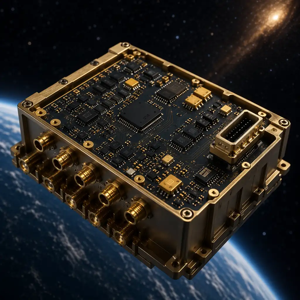
Industries / Aerospace & Defense
AS9100D-ready manufacturing. MIL-PRF-31032 & IPC Class 3A capability. Rogers, PTFE, ceramic, and polyimide substrates for satcom, avionics, radar, navigation, and flight control, where failure is not an option.
Manufacturing Excellence
Single-sided to 32-layer HDI . From simple control boards to complex satcom backplanes with blind/buried vias, back-drill, and any-layer microvia stacking.
Ultra-fine line capability for high-density avionics and radar modules. Laser-drilled 75µm microvias on any-layer HDI builds. Impedance ±5% verified by TDR.
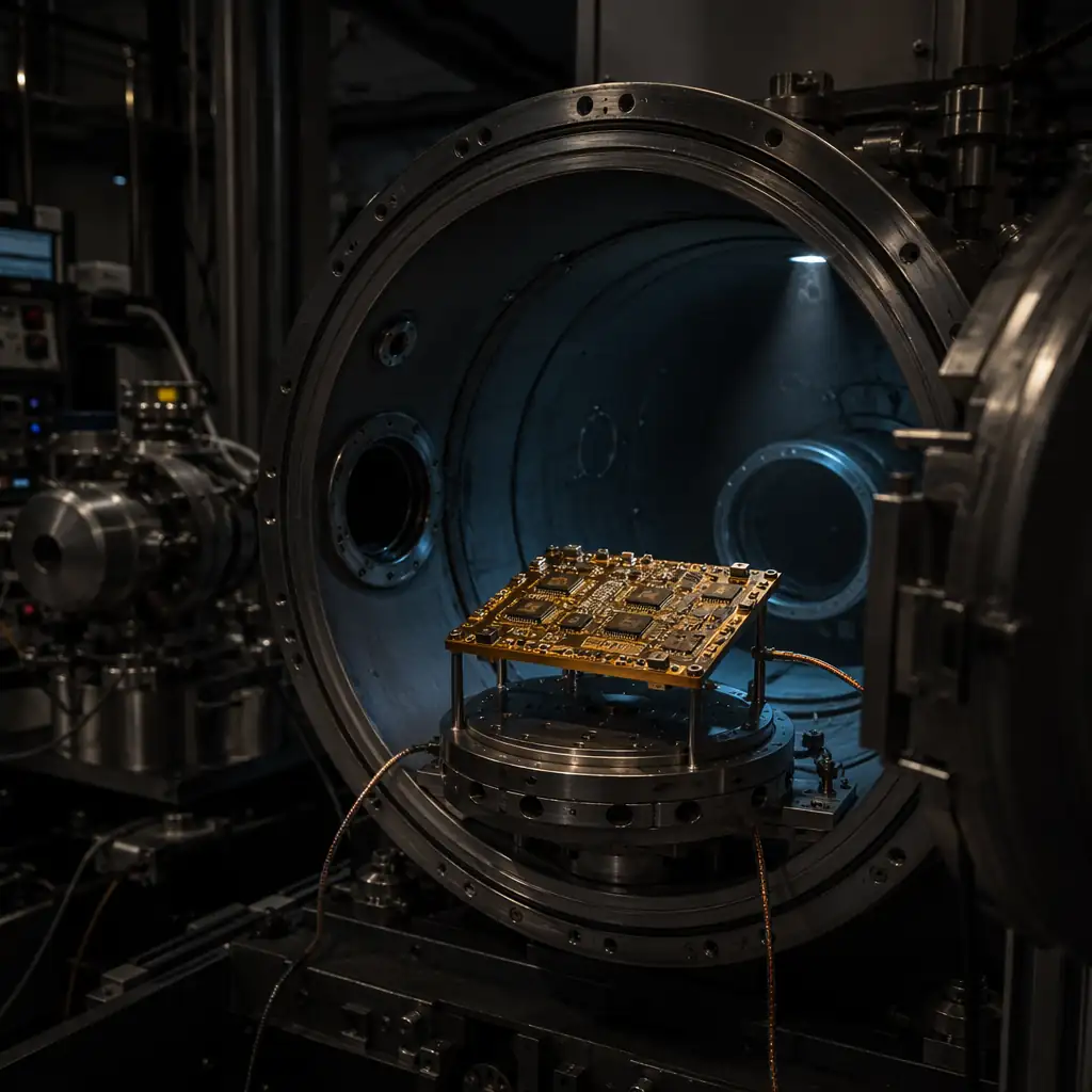
Polyimide (Tg 250°C+), PTFE, ceramic, and Rogers substrates qualified for extreme thermal cycling, 500+ cycles without delamination. Outgassing compliant per ASTM E595.
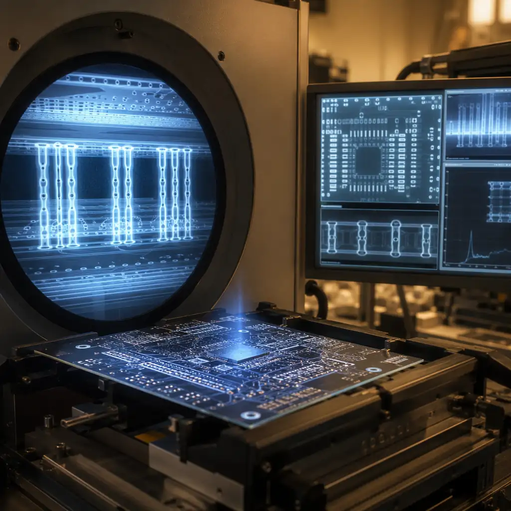
Every board passes AOI and X-Ray. Destructive Physical Analysis (DPA) available per MIL-PRF-31032, micro-sectioning, solder joint analysis, and intermetallic verification. Full lot traceability.
TDR-verified on every production panel. Critical for RF front-ends, phased-array radar, satcom up/down converters, and high-speed digital backplanes. Rogers 4350B/4003C and PTFE laminates in stock.
IPC Class 3A acceptance criteria, the most stringent in the PCB industry. 100% electrical test. Microsection coupons on every panel. Process FMEA. Certificate of Conformance with every shipment.
Why MIL-Spec Matters
MIL-PRF-31032 and IPC-6012 Class 3A define the highest reliability tier in PCB manufacturing. Every aspect, from laminate selection to plating thickness, from annular ring to solder mask adhesion, is specified tighter, tested harder, and documented deeper. We build to these standards because in aerospace, there is no "acceptable failure rate."
Materials & Survivability
Aerospace PCBs operate in conditions that degrade ordinary materials rapidly, vacuum outgassing, rapid thermal swings, continuous vibration, and radiation exposure. We select every laminate, prepreg, and surface finish for proven performance in these environments.
| Application | Key PCB Requirements | Huaxing Capability | Quality Level |
|---|---|---|---|
| Satcom / Telemetry | Rogers/PTFE, impedance ±5%, 20+ layers, ENIG | Rogers 4350B/4003C, hybrid FR-4+Rogers, back-drill | IPC Class 3A |
| Avionics / Flight Control | Polyimide, IPC Class 3A, −55 to +125°C, 15yr life | Polyimide, 32 layers, 100% AOI+X-Ray, DPA | IPC Class 3A |
| Radar / EW Systems | Rogers/PTFE hybrid, ±5% impedance, 0.3mm BGA | Mixed laminate, any-layer HDI, 75µm µvias, TDR | IPC Class 3 |
| Navigation / GNSS | PTFE ultra-low Dk, precision RF traces, 6-12 layers | PTFE, Rogers, ENEPIG, ±5% impedance control | IPC Class 3 |
| Missile / Ordnance | High-Tg, vibration-resistant, ceramic, 6-16 layers | Ceramic Al₂O₃/AlN, polyimide, heavy copper 6oz | IPC Class 3A |
| Satellite Power Bus | Heavy copper, 4kV HiPot, thermal management, 6-20 layers | 6oz copper, metal-core, 4kV HiPot, conformal coating | IPC Class 3A |
Laminate, prepreg, and surface finish selected per MIL-PRF-31032 or IPC-4101 slash sheets. Outgassing verification per ASTM E595.
PFMEA before production. Design review against IPC-6012 Class 3A requirements. Coupon layout plan.
Class 3A-compliant etch, plate, and lamination. Back-drill and impedance TDR verification. Microsection coupon at first article.
AOI + X-Ray on every board. Flying probe or bed-of-nails 100% electrical test. Visual to IPC-A-600 Class 3A.
Destructive Physical Analysis on sample coupons. Certificate of Conformance with lot traceability. Final packaging per MIL-STD-2073.
Remove unused via stubs for signal integrity above 5 Gbps. Controlled-depth back-drill with ±50µm tolerance. Critical for high-speed digital backplanes.
Wrap-around copper plating on board edges for EMI/RFI shielding, grounding, and thermal conduction. Common in avionics enclosures and radar modules.
Hard gold edge connectors with nickel underplate. 30μ" or 50μ" gold thickness. Beveled edges for smooth insertion. Common in line-replaceable units (LRUs).
Acrylic, silicone, or urethane selective coating for humidity, salt-spray, and fungus protection. MIL-I-46058 qualified. UV tracer for inspection.
Time Domain Reflectometry on every impedance-controlled net. ±5% tolerance. Test report included with CoC. Critical for RF and high-speed digital.
500-cycle thermal shock from −55°C to +125°C per IPC-TM-650. IST (Interconnect Stress Testing) available. Verifies barrel integrity and laminate reliability.
Send us your design files and specification requirements. MIL-PRF-31032, IPC Class 3A, AS9100. Our engineering team will respond within 24 hours with a DFM analysis, material recommendation, and qualification timeline.

Upload your Gerber files and specification requirements. We'll respond within 24 hours with DFM review, material recommendation, and qualification timeline.