
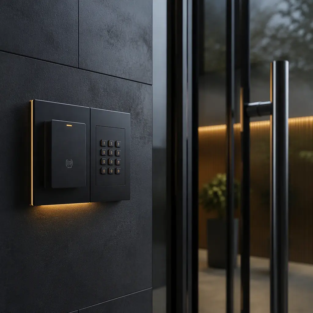
An access control system is a handful of small boards with an outsized responsibility: a controller panel that decides who enters, card readers at the door, and electric locks that physically stop people. A single controller typically manages 1–4 doors, and each door combines a lock output, a reader input, a door-position sensor, a request-to-exit (REX) button and often a siren. All wired back to one PCB that must also talk to the network and survive a power cut.
The design stakes are unusual. A lock that fails closed traps people; a lock that fails open lets people in. Both are wrong, and both are board-level decisions: the lock output circuit, the battery-backup path and the fire-alarm input are designed on the schematic before the first component is placed. Huaxing PCBA builds access control boards for security manufacturers in 20+ countries, and this guide covers the layout and protection decisions that show up in UL 294 and EN 60839 evaluations.
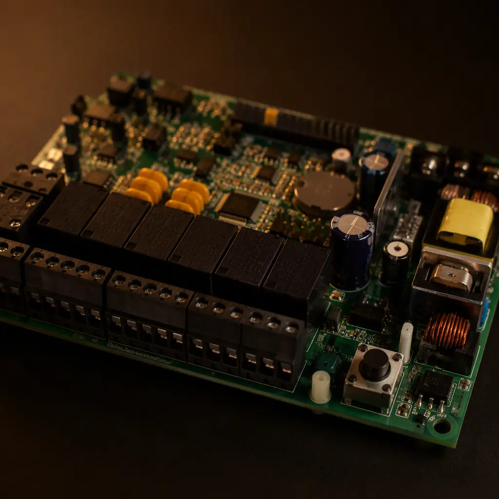
Controller Architecture: What a Multi-Door Board Must Handle
Most commercial access control panels share the same block structure, and the PCB is organized around it:
| Subsystem | Interface | Electrical Reality |
|---|---|---|
| Electric lock output | 12/24 V relay or electronic switch | 1–3 A inrush; flyback from inductive coils |
| Card reader input | Wiegand (legacy) or OSDP/RS-485 (modern) | 5 V TTL data lines; 100 m+ cable runs |
| Door sensors | Dry contact (reed switch, REX, tamper) | Low-voltage sense lines with debounce |
| Network | 10/100/1000BASE-T PoE | 802.3af/at/bt power from the same cable |
| Battery backup | 12 V sealed lead-acid or Li-ion | Charger + deep-discharge protection |
The trend is toward smaller, PoE-powered panels, one reader and one lock per enclosure, managed centrally over Ethernet, but the electrical problems are the same at every scale. Our smart lock PCB guide covers the single-door consumer side; this guide focuses on the multi-door and enterprise hardware. The security software and cryptography side of the system is covered in our IoT hardware security guide.
Key Takeaway: Design the lock output and the battery path first, they are the safety functions. Reader interfaces and network connectivity are added around them, not the other way around.
Lock Outputs: Fail-Safe vs Fail-Secure and the Circuits Behind Them
Every door decides between two lock behaviors. Fail-safe locks (magnetic locks) release when power is lost; fail-secure locks (electric strikes, most deadbolts) stay locked when power is lost. The PCB must support both, and the choice drives the power design.
Relay or solid-state? Both need flyback protection
Lock coils are inductive: a magnetic lock draws 500 mA at 12 V steady-state but the relay or MOSFET switching it off generates a voltage spike that destroys silicon without a freewheeling diode or TVS across the load. Place the clamp component within 5 mm of the switch, and parallel the relay contacts with a snubber for DC loads. Contact ratings should be 2–3× the lock's inrush.
Current sensing and lock-health feedback
Modern controllers monitor lock current to detect a stuck door or a failed lock: a sense resistor in the lock loop feeds the MCU's ADC, and the firmware alarms when current is out of the expected window. The sense resistor needs Kelvin-style routing, separate sense traces to the resistor pads, not tapped off the high-current trace. Current-sense layout practice is covered in our trace width and current guide.
Fire alarm input: the unlock override
Building codes require fail-secure doors to unlock on fire alarm. The fire-alarm input is a dry contact that must force the lock output off regardless of MCU state, implement it as a hardware override (the alarm contact in series with the lock drive), not as firmware. This is the single most audited function in UL 294 testing. Related life-safety board practice is in our fire alarm PCB guide.
Reader Interfaces: Wiegand Legacy, OSDP and Isolation
Card readers connect over two fundamentally different interfaces, and many panels must support both.
Wiegand: simple but electrically exposed
The Wiegand interface is two open-collector data lines (DATA0/DATA1) at 5 V, typically 26-bit or 40-bit frames. It is unencrypted and easy to tap, which is why it is legacy, but the installed base is enormous. On the PCB, Wiegand inputs need pull-ups, ESD protection and series resistance, because the wires run unprotected through walls to the door. Input protection practice is detailed in our ESD control guide.
OSDP over RS-485: the modern standard
SIA OSDP replaces Wiegand with an AES-128-encrypted, supervised RS-485 bus, readers report health, and tampering is detected. RS-485 on the PCB needs proper termination (120 Ω at both ends, selectable via jumper), common-mode protection, and differential routing with the pair twisted and kept together. Our RS-485/RS-232 design guide covers transceiver selection and termination in depth.
Surge protection on outdoor runs
Reader and lock wires leave the building; lightning-induced surges are a leading cause of controller board failures. Every field-wired terminal needs a TVS or MOV to ground plus series resistance on data lines, and the board's ground must be connected to the enclosure and building earth at one defined point. Panels rated for outdoor reader connections follow the transient test levels in UL 294 and EN 60839-11-1. Our EMI/EMC guide covers transient protection architecture.
Power: PoE, Battery Backup and the Never-Open-Never-Stuck Budget
Access control hardware must keep working when the mains fails. That is the entire point of securing a door. Power design is therefore a chain: PoE or AC adapter, battery charger, and the switchover logic.
PoE-powered panels: budget the watts honestly
A reader plus one strike plus the controller MCU easily exceeds 802.3af's 15.4 W, most panels spec 802.3at (30 W) or 802.3bt (60–90 W) for multi-door enclosures. The PoE front end needs the magnetics, PD controller and DC-DC converter laid out as a tight, isolated section; transformer placement and thermal management follow the rules in our PoE design guide.
Battery backup with correct charging
The classic backup is a 12 V 7 Ah sealed lead-acid cell: charged at a float voltage of 13.6–13.8 V, current-limited, with reverse-polarity and deep-discharge protection. The charger is a small power stage, it gets the same flyback, thermal and copper-weight attention as the lock outputs. Panels with fail-secure strikes on battery backup must budget battery runtime at full lock load, not idle current. Battery system layout is covered in our energy storage guide.
Power sequencing and brownout behavior
The MCU must come up after the lock supply is stable, and on brownout it must release the lock into its defined state before the rail collapses. A supervised power supervisor with a defined reset threshold and lock-release logic is the difference between a panel that misbehaves on a flicker and one that does the right thing. Power integrity and supervisor layout are in our power integrity guide.
Network, Enclosure and the Board's Mechanical Life
The controller board lives in a metal or plastic enclosure, often in a comms closet or above a door, dusty, humid, and reachable by installers with screwdrivers.
Ethernet and isolation
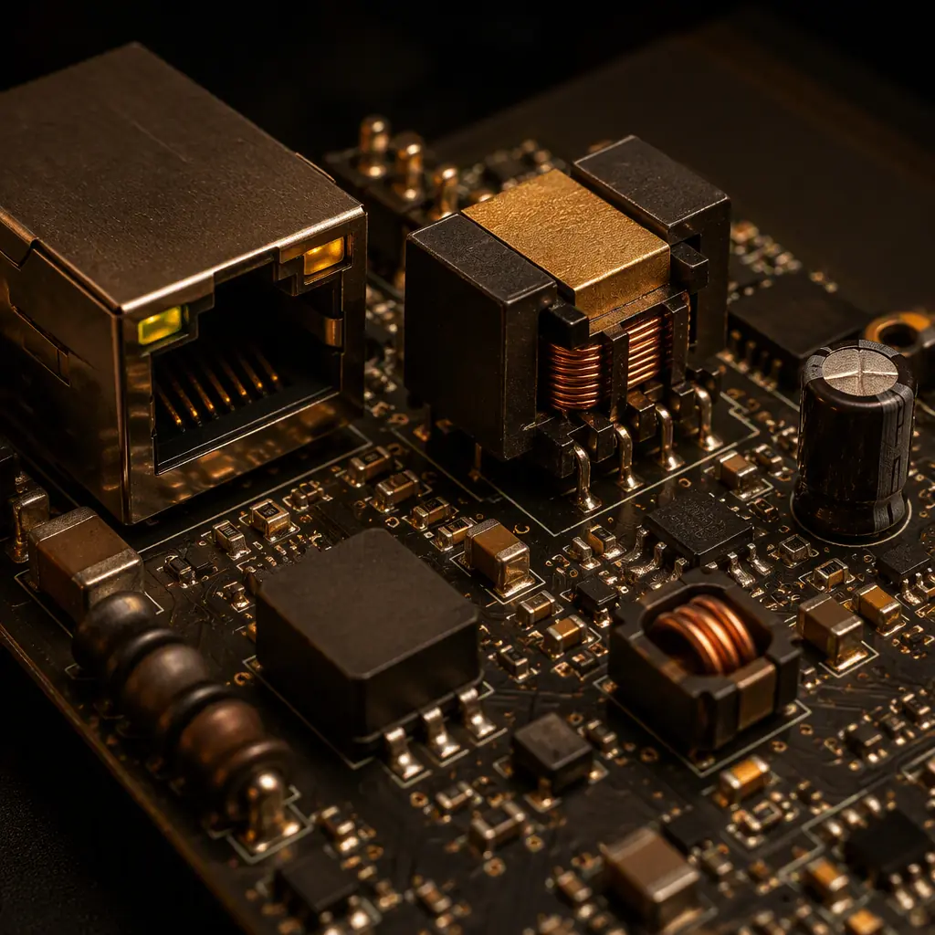
The network section needs the PHY transformer, common-mode chokes and ESD protection arranged as a defined Ethernet island with the magnetics placed right at the RJ45. Ethernet PHY layout rules, differential pairs, impedance, ground cuts under the magnetics, are covered in our Ethernet PHY guide, and the network switch/router side in the networking PCB guide.
Conformal coating and terminal placement
Controllers in humid or outdoor-adjacent locations get conformal coating. But the field-wired terminal blocks stay uncoated, and the coating mask must be defined in the board drawing. Coating types and masked zones are detailed in our conformal coating guide. Terminal blocks should be grouped by voltage class on the board edge, with the mains and SELV sections separated by the required creepage.
Tamper detection and mechanical integrity
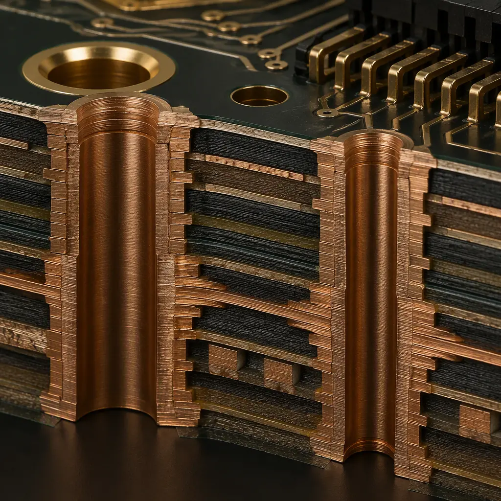
Panels include tamper switches that alarm when the cover opens. The tamper input needs debounce and a defined fail state. Mounting holes need annular ring reinforcement (the board is often held by two screws with the relays flexing nearby), and the relay section should be stiffened or placed away from the mounting points. Mechanical stress and hole design are covered in our manufacturing tolerances guide.
Reliability Reality: Access control boards fail in the field in a predictable order: surge damage on reader/lock lines, relay contact wear, and battery chargers that cook the backup cell. All three are design decisions made on the schematic, protect the terminals, derate the relay, and temperature-compensate the charger.
Manufacturing and Certification of Access Control Boards
Access control hardware is certified, and the certification requirements shape the board.
UL 294 and EN 60839-11-1 design implications
UL 294 (access control system units) evaluates standby power, line surge and endurance. The lock output must survive thousands of cycles, and the board must pass the transient tests on every field-wired terminal. Component spacing, trace widths on the surge paths and the grounding scheme are all part of the evaluation. Our UL certification guide maps the requirements to layout actions.
Testing: relay endurance, surge and thermal
Production testing covers lock-output function under load, battery charger behavior, network link quality and the fire-alarm override. Burn-in at elevated temperature catches marginal solder joints on the relay and power sections. Test strategy comparison is in our testing methods guide, and relay/solder reliability in the IPC class guide.
Summary: The Access Control Board Checklist
Design the safety chain first, lock outputs with flyback protection, hardware fire-alarm override, battery backup with correct charging, then add reader interfaces with surge protection, PoE power, and Ethernet isolation. Group terminals by voltage, coat the board, reinforce the mounting holes, and validate against UL 294 or EN 60839-11-1 before production.
At Huaxing PCBA, we assemble access control boards with 0201 passives, through-hole relays and PoE magnetics across 8 SMT lines, with selective soldering for the power and relay sections and X-ray inspection on every BGA. Our engineering team reviews surge protection, creepage and lock-output drive during the free DFM check. Read our video intercom design guide for the adjacent door-station hardware, or contact us with your controller design for a manufacturing review.
