
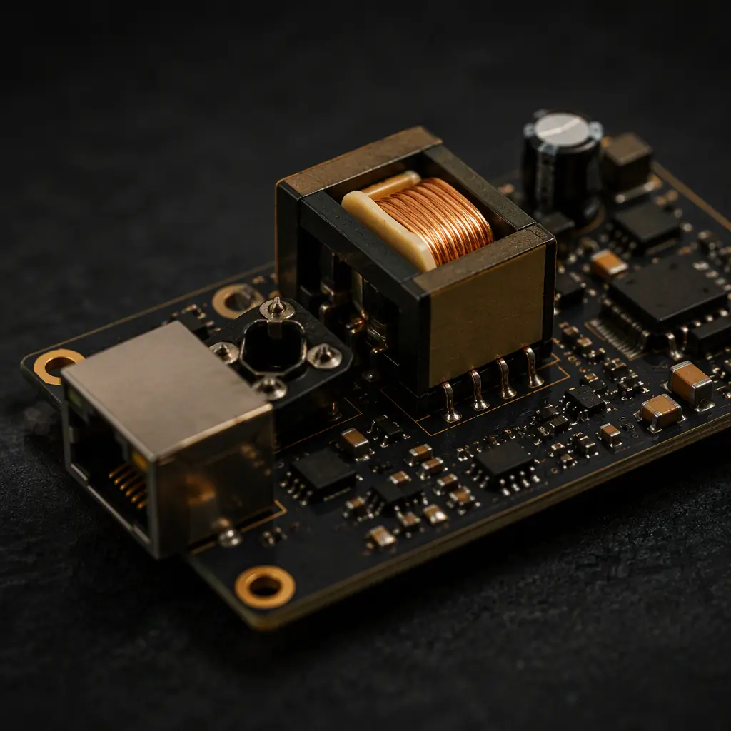
Power over Ethernet (PoE) has moved from a convenience to a default: IP cameras, access points, LED controllers, building automation nodes, and industrial sensors increasingly ship with a single RJ45 expecting both link and power. That single port hides a demanding design problem — a PoE powered device (PD) board carries 48–57 V DC alongside gigabit differential pairs, switching power electronics, and isolation boundaries, all in a compact footprint.
Huaxing PCBA manufactures PoE PD and PSE boards for network and building automation customers, up to 32 layers, with the isolation and thermal controls that 802.3bt class 8 designs require. This guide covers the power classes, the front-end layout, the isolation rules, and the manufacturing checks that separate a passing design from a field failure. If you are new to the power side, our power integrity and PDN design guide covers the fundamentals first.
802.3af, at, and bt: The Power Classes You Are Designing For
The PoE standard has grown three times. Each revision raised the power budget and tightened the front-end requirements. Designing a PD that only needs 13 W against the wrong class wastes cost; designing a 90 W PD without planning the thermal path fails in the field.
| Standard | PSE Output | PD Budget | Class Range | Typical Use |
|---|---|---|---|---|
| 802.3af (PoE) | 15.4 W | 12.95 W | 0–3 | Legacy IP cameras, VoIP |
| 802.3at (PoE+) | 30 W | 25.5 W | 4 | PTZ cameras, thin clients |
| 802.3bt (PoE++) | 60 W | 51 W | 5–6 | LED signage, access points |
| 802.3bt (PoE++) | 90 W | 71.3 W | 7–8 | PTZ+heaters, industrial PCs |
Class 5–8 designs use all four twisted pairs (4-pair power) instead of two, which changes both the diode bridge configuration and the DC-DC input stage. For network infrastructure boards, our switch and router PCB guide covers the PSE side — where the port count drives the power budget and the thermal design.
The PD Front End: Detection, Classification, and the Diode Bridge
Every PoE PD starts with the same front end: a signature resistor (24.9 kΩ) for detection, a classification circuit, and a diode bridge that rectifies the DC regardless of cable polarity. The bridge is where cost and loss decisions happen — for 802.3bt class 8, the bridge must carry up to 1.5 A per pair continuously, and standard small-signal diodes are not enough.
Layout rules for the front end are strict: the signature and classification circuitry must sit close to the connector with short traces, and the bridge diodes need enough copper and thermal relief to shed heat. A common field failure is the detection signature drifting out of the 23.75–26.25 kΩ window because the resistor was placed next to a heat source or its traces added parasitic resistance. Keep the front-end components in a cool, quiet zone of the board.
Isolation and Creepage: The 1500V Barrier Nobody Draws
PoE front ends are galvanically isolated from the downstream electronics — typically 1500 Vrms isolation between the PoE side and the DC-DC output. That isolation is not just a transformer choice; it is a physical layout requirement. Creepage (distance along the board surface) and clearance (through air) must be designed, not assumed.
Plan the Isolation Slot
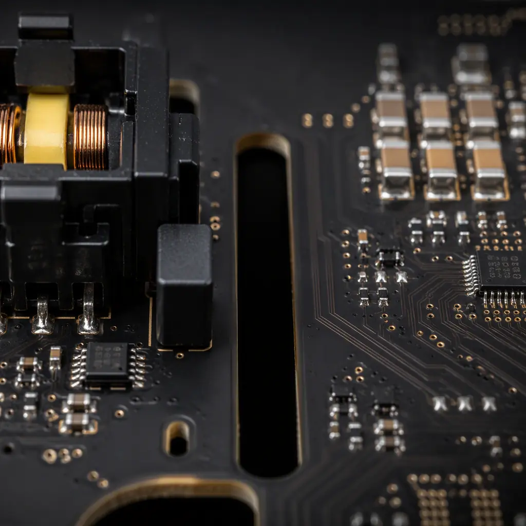
A routed slot (moat) under the isolation transformer physically separates the primary and secondary grounds. Without it, a solder bridge or whisker across the boundary turns a compliance-passing design into a safety failure. Slot width should match the creepage requirement plus margin.
Size the Creepage for Your Pollution Degree
For 1500 Vrms working voltage with pollution degree 2, IPC-2221 creepage lands around 1.5–2 mm minimum — but add margin for coated boards, and never route other signals across the boundary. The transformer's own clearance spec is a floor, not the target.
Keep the DC-DC Switching Node Away from the Data Pair
The flyback or buck switching node carries high dv/dt. Keep it on the opposite side of the board from the magnetics, or shield it with a ground pour. Our EMC and EMI compliance guide covers the coupling paths that cause radiated failures.
Thermal Design: 90W Through a Small Board
At 71.3 W delivered, a class 8 PD dissipates several watts in the front-end bridge, the DC-DC converter, and the magnetics. A typical 90% efficient 71 W converter still sheds 7 W of heat — enough to raise board temperature dramatically in a sealed enclosure. Thermal design is not optional at this power level.
Use Thermal Vias Under Power Components
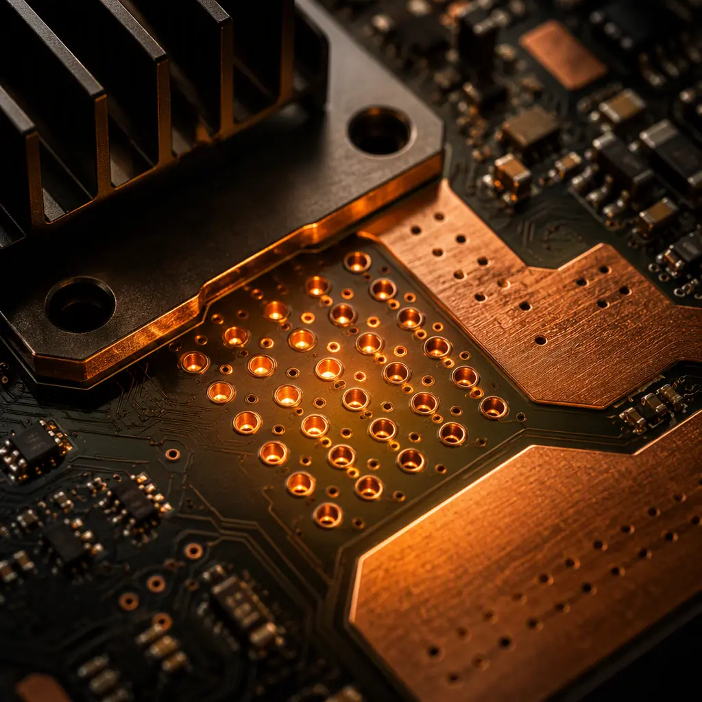
The MOSFETs and bridge diodes need thermal via arrays tied to internal copper planes. For a 1.6 mm board, a 3×3 array of 0.3 mm vias under each power device can drop junction temperature 15–20°C versus no vias. Our thermal management guide covers via sizing and plane design in detail.
Plan the Copper Pour Budget Early
At 1.5 A per pair, trace and plane width matter. A 2 oz copper pour carrying 1.5 A with a 10°C rise needs roughly 0.5 mm width minimum — but for the 4-pair 802.3bt path, plan dedicated pours, not traces, and keep them on adjacent layers connected with stitching vias.
Position the Converter Where Air or Enclosure Metal Can Help
Thermal vias to a board edge or to a pad that contacts the enclosure metal turn the case into a heatsink. If the design cannot do that, at minimum keep the DC-DC section away from the processor and the detection circuitry.
Key Takeaway: For class 5–8 designs, layout the thermal path before you layout the signals. Thermal vias, dedicated pours, and component placement decisions made at schematic time cost nothing; retrofitted at layout review they cost a board revision.
The Data Side: Magnetics and Differential Pairs
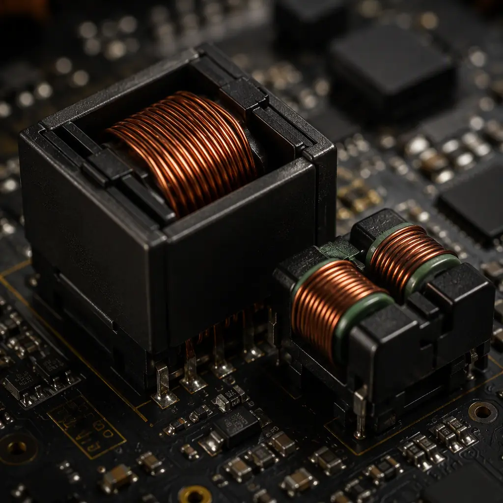
PoE adds power to an Ethernet link, and the Ethernet side still has to work at gigabit speed. The magnetics module (or discrete transformer + common-mode choke) provides both isolation and common-mode termination, and its placement directly affects link quality.
Place the magnetics as close to the RJ45 as physically possible, keep the differential pairs length-matched and impedance-controlled to 100 Ω, and route them over a solid reference plane with no splits — especially no split under the magnetics. For the high-speed layout rules, our signal integrity guide and crosstalk analysis guide cover pair routing, via transitions, and return-path discipline in detail.
Manufacturing Checks for PoE Boards
PoE boards concentrate the manufacturing risks of both power and high-speed boards: high-voltage spacing, thermal relief, and impedance control all in one product. Before production, verify four things:
Copper Weight and Plating for Current
Confirm the copper weight matches the current plan — 2 oz or heavier for the 4-pair power path. Our copper weight selection guide explains the trade-offs of thick copper on fine-pitch signal layers.
Impedance Coupons for the Data Pairs
Require impedance test coupons for the 100 Ω differential pairs, measured per your stackup. Do not accept "designed to 100 Ω" — accept measured values. Our impedance control guide has the coupon specification template.
Isolation Testing at Incoming Inspection
Run a hipot or insulation resistance check across the isolation boundary on a sample. A 1500 Vrms-rated barrier that tests at 200 V before shipment is a defect, not a surprise for later.
Confirm the Isolation Slot Is Real
Verify the routed slot exists in the fabricated board — we have seen DFM tools silently bridge a slot with copper pour. X-ray or cross-section a first article if the board is small enough that the slot is hard to see. Our first article inspection guide lists the checks.
Summary: The PoE Board Is a System, Not a Schematic
A reliable PoE design coordinates four disciplines: the power budget (which class you target), the front-end (detection, bridge, classification), the isolation boundary (creepage, slots, transformer placement), and the thermal path (vias, pours, component position). Get all four right and the board passes compliance the first time; miss one and the field failure is expensive.
At Huaxing PCBA, we manufacture PoE PD and PSE boards with controlled impedance, isolation-slot verification, and 2 oz+ copper capability. Read our EMC compliance guide for the test-side companion, or send your design for a DFM review focused on the PoE-specific risks before you commit to tooling.
