
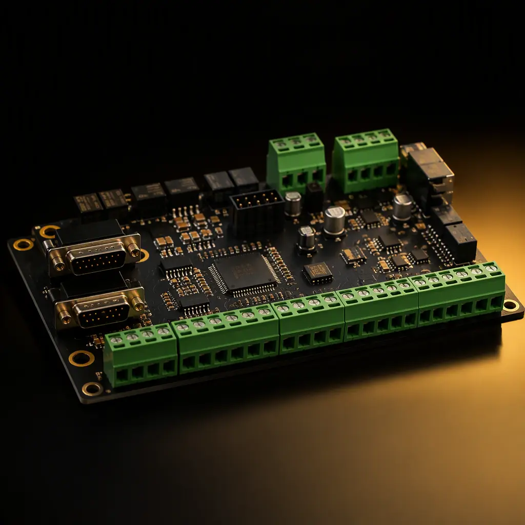
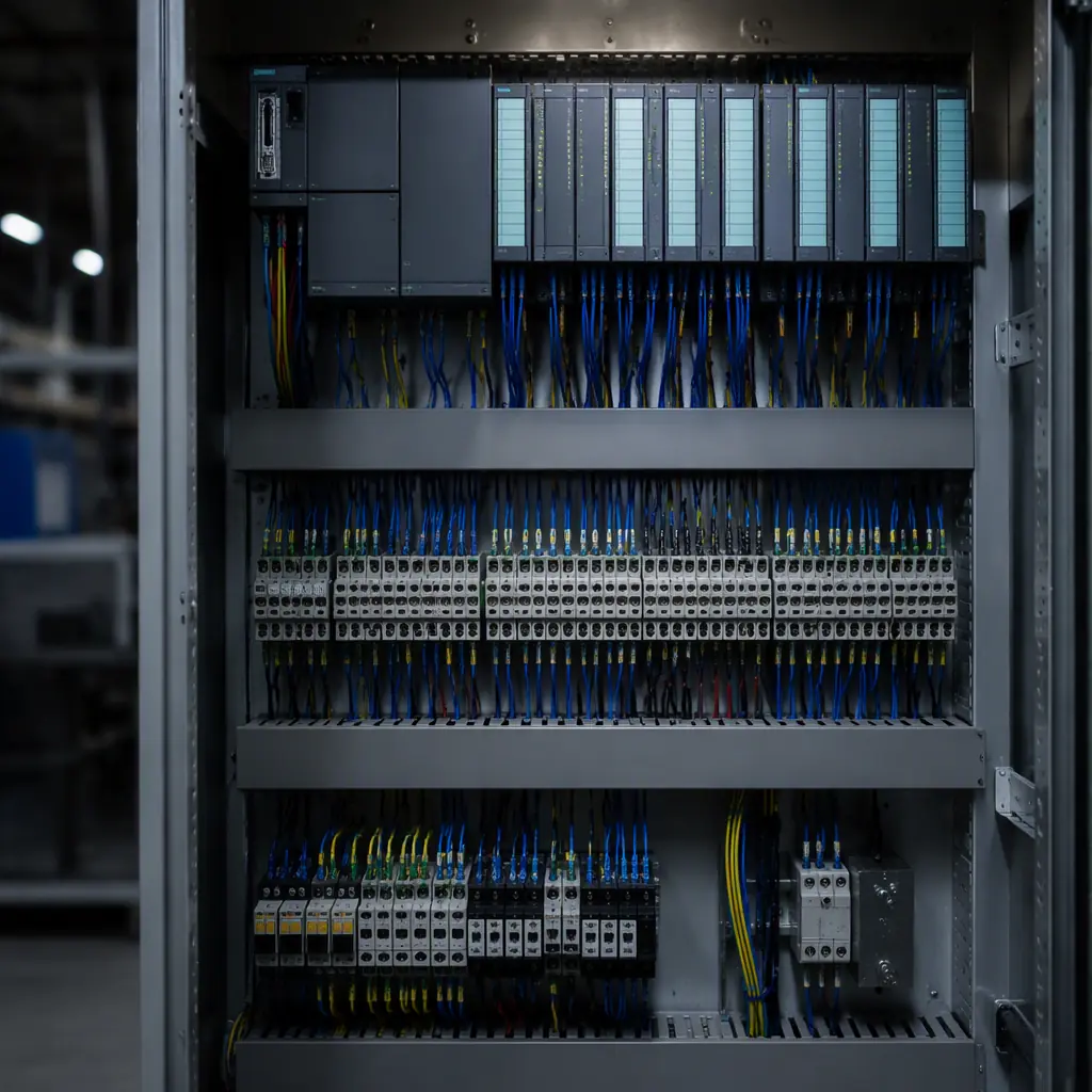
Industrial control panels, building automation controllers, solar inverters, wind turbines, smart meters and factory robots share one quiet secret: their inter-device communication mostly runs over RS-485 at 9.6 kbps to 10 Mbps, on two twisted wires, using protocols like Modbus RTU and BACnet MS/TP. RS-485 has outlived every faster and smarter bus because it is differential, robust, cheap, and simple. But only when the transceiver circuit is laid out and protected correctly.
Huaxing PCBA manufactures industrial control and IoT boards for PLCs, HVAC controllers, solar and wind systems, and smart metering customers: including RS-485/RS-232 interfaces with isolation, surge protection, and full functional test. This guide covers transceiver selection, termination and biasing, layout rules, ESD/surge protection, RS-232 level shifting, isolated RS-485, and the manufacturing checks that keep field failures at zero.
Why RS-485 Still Runs the Factory Floor
RS-485 is a differential signaling standard: the data is the voltage difference between two wires (A and B), not a voltage to ground. That single property is why it dominates industrial networking, differential receivers reject common-mode noise, and the standard allows 32 unit loads on one bus, up to 1200 m of cable at low baud rates, and multiple transmitters on the same pair.
Know What You Are Competing Against
CAN handles 1 Mbps over ~40 m; Ethernet solves long distance but needs switches, magnetics and more complex MCUs; wireless adds latency and reliability questions. RS-485 wins where you need 32+ devices, kilometers of wiring, and deterministic polled communication on a two-wire budget. Which is why Modbus RTU remains the most deployed industrial protocol in the world.
Match the Transceiver to the Topology
Two-wire half-duplex (most Modbus RTU networks) needs a transceiver with driver/receiver enable pins and direction control from the MCU. Four-wire full duplex (rare, used for point-to-point) uses separate transmit and receive pairs. Newer transceivers integrate auto-direction, termination, and even surge protection. At a cost premium that is often worth it for compact designs.
Size the Bus: Nodes, Cable Length, and Baud Rate
The classic limits: 32 unit loads (modern transceivers are 1/8 or 1/4 load, allowing 128–256 nodes), 1200 m maximum cable, and a baud-rate/distance tradeoff. 9600 baud runs the full 1200 m, while 10 Mbps is limited to roughly 15–30 m. Your PCB layout cannot fix a network designed beyond these limits, so specify the topology before the schematic.
| Protocol / Bus | Typical Speed | Max Distance | Topology |
|---|---|---|---|
| Modbus RTU over RS-485 | 9.6 kbps–115.2 kbps | 1200 m | Multidrop, half-duplex |
| BACnet MS/TP | 9.6–76.8 kbps | 1200 m | Multidrop, half-duplex |
| DMX512 (lighting) | 250 kbps | ~500 m | Daisy chain |
| Profibus DP | 9.6 kbps–12 Mbps | 100–1200 m | Multidrop, RS-485 |
| RS-232 point-to-point | ≤115.2 kbps | ~15 m | Single-ended, 1:1 |
Termination and Fail-Safe Biasing
Two resistors decide whether an RS-485 network works at all: the termination resistor at each end of the bus, and the fail-safe bias network that defines the idle state. Getting these right on the PCB is the difference between a network that boots clean and one that throws random CRC errors.
Terminate With 120 Ω at Both Physical Ends of the Cable
The characteristic impedance of standard twisted-pair cable is about 120 Ω, and the bus needs a matching resistor at each end to absorb reflections. The termination belongs at the physical cable ends, not at every node. Many designs place a 120 Ω footprint on the PCB, populated only for end devices. Use a 0 Ω or DIP-switch option so field installers can enable it without soldering.
Add Fail-Safe Biasing So an Idle Bus Reads as a Valid Mark
With no transmitter active, the bus floats and a standard receiver may read random bits. Fail-safe biasing (pull-up on A, pull-down on B, typically 390–680 Ω with a 5 V supply, or transceivers with built-in fail-safe) forces the idle differential voltage above the receiver's threshold so the bus reads as a defined logic 1. The bias resistors must sit at the nodes that provide the termination: usually the master, and their values interact with the termination resistance, so calculate the divider, don't guess.
Put the Protection Network Between the Transceiver and the Connector
The physical layer order from cable to chip should be: connector → series/current-limit or common-mode choke → TVS diodes to ground → (optional gas discharge tube for severe surge) → transceiver pins. The TVS clamps fast transients; the common-mode choke rejects cable-coupled noise; the series resistance (10–50 Ω) limits fault current. Place these in exactly that order along the trace.
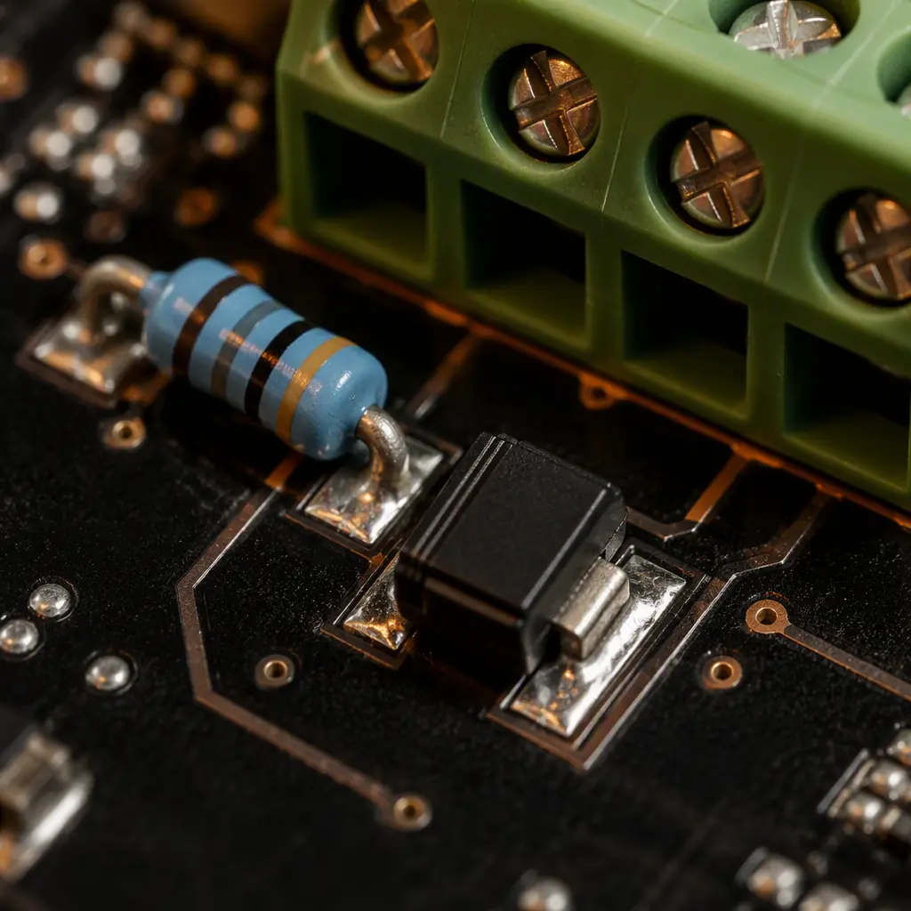
Transceiver Layout: Decoupling, Placement and Ground
At RS-485 speeds the layout is forgiving compared to high-speed digital. But the transceiver sits at the edge of the board, connected to outdoor cabling, inside an industrial enclosure full of relays, contactors, and motor drives. The layout must protect the interface from the board's own noise.
Decouple the Transceiver With 0.1 µF Right at the Power Pin
The transceiver's supply pin needs a 0.1 µF ceramic capacitor within 2–3 mm, plus a 1–10 µF bulk capacitor nearby. Driver switching current spikes flow through this decoupling; a long trace to the cap turns the supply pin into a noise source that couples into the receiver's differential inputs. Keep the transceiver's ground pin tied to the board ground plane with a short, direct via.
Route the A/B Lines as a Tight Differential Pair, Away From Switching Nodes
On the board, the A and B traces should run together (5–10 mil spacing), equal length, with a solid ground plane underneath. Keep them away from switching power traces, relay coils, and the MCU's crystal. If the board carries high-current motor or heater drives, a ground guard trace or a slot between the noisy section and the interface section prevents coupling. For high-baud designs (1 Mbps+), treat the pair as controlled-impedance differential (100–120 Ω), see our signal integrity guide for the routing rules.
Place the Connector at the Board Edge, Near the Transceiver
The cable should enter the board and reach the transceiver with minimal detour. A long meandering trace from connector to transceiver turns the interface into an antenna. Place the connector, protection network, and transceiver in a straight line. This is the single most visible layout difference between a professional industrial board and a hobby design.
ESD and Surge Protection for Industrial Cables
RS-485 cables run between buildings, across factory floors, and alongside power wiring. They collect electrostatic discharge, induced surges from lightning strikes, and fault voltages from miswiring. The transceiver alone cannot survive these. The protection network is a required circuit, not an option.
Use TVS Diodes Rated for the Actual Threat Level
For general ESD (IEC 61000-4-2), a low-capacitance TVS (e.g. 600 W class, < 5 pF) on each line to ground is enough. For outdoor or lightning-prone installations, add a gas discharge tube (GDT) ahead of the TVS and a series impedance between them, sized for IEC 61000-4-5 surge levels. Specify the protection level in your requirements — a building automation controller and a solar farm string monitor need different surge ratings.
Add a Common-Mode Choke Between Connector and Transceiver
A small common-mode choke (often integrated in industrial transceiver front-ends) blocks cable-coupled common-mode noise from reaching the receiver's sensitive inputs while passing the differential signal untouched. It also helps pass radiated emissions testing. The cable is the antenna, and the choke breaks the antenna's coupling into the board.
Never Let Protection Ground Currents Flow Through the Logic Ground
The TVS ground connection must go straight to the chassis/earth ground point, not through the MCU's ground plane. A surge event dumps potentially hundreds of amps into the protection ground. If that current flows through the logic ground plane, it will destroy the MCU even though the transceiver survived. Use a separate protection ground island connected at a single point, or an isolated design as described below.
RS-232: Level Shifters and Connector Layout
RS-232 is the point-to-point legacy interface: single-ended, ±12 V signaling, used for debug ports, configuration, and legacy equipment. Modern boards use 3.3 V transceivers like the MAX3232 that generate the ±5 V rail internally from a charge pump.
Keep the Charge-Pump Capacitors Close to the Level Shifter
The MAX3232-style transceivers need four 0.1–1 µF charge-pump capacitors; place them within 5 mm of the IC's pins with short traces. A distant capacitor starves the charge pump, dropping the output voltage below the RS-232 threshold and causing intermittent link failures that are infuriating to debug in the field.
Route TX and RX as a Pair to the DB9 or Header, Add ESD Clamps
RS-232 lines are single-ended and vulnerable to ESD through the connector, add TVS diodes on both TX and RX near the connector. Keep the pair short and away from switching supplies. For debug ports, bring the signals to a standard 0.1" header with a defined pinout, and label it, a mislabeled debug header wastes more engineering hours than any other board feature.
Support the Voltage Domains You Actually Use
Legacy RS-232 gear expects ±12 V and may not work correctly with the ±5 V from a charge-pump transceiver. If the product must talk to old PLCs or industrial PCs, specify a transceiver with adequate swing or a true RS-232 level. Check the MCU's UART pins for 5 V tolerance. A 3.3 V-only MCU driving a 5 V transceiver needs level shifting on the logic side too.
Isolated RS-485: When the Bus Ground Is Not Your Ground
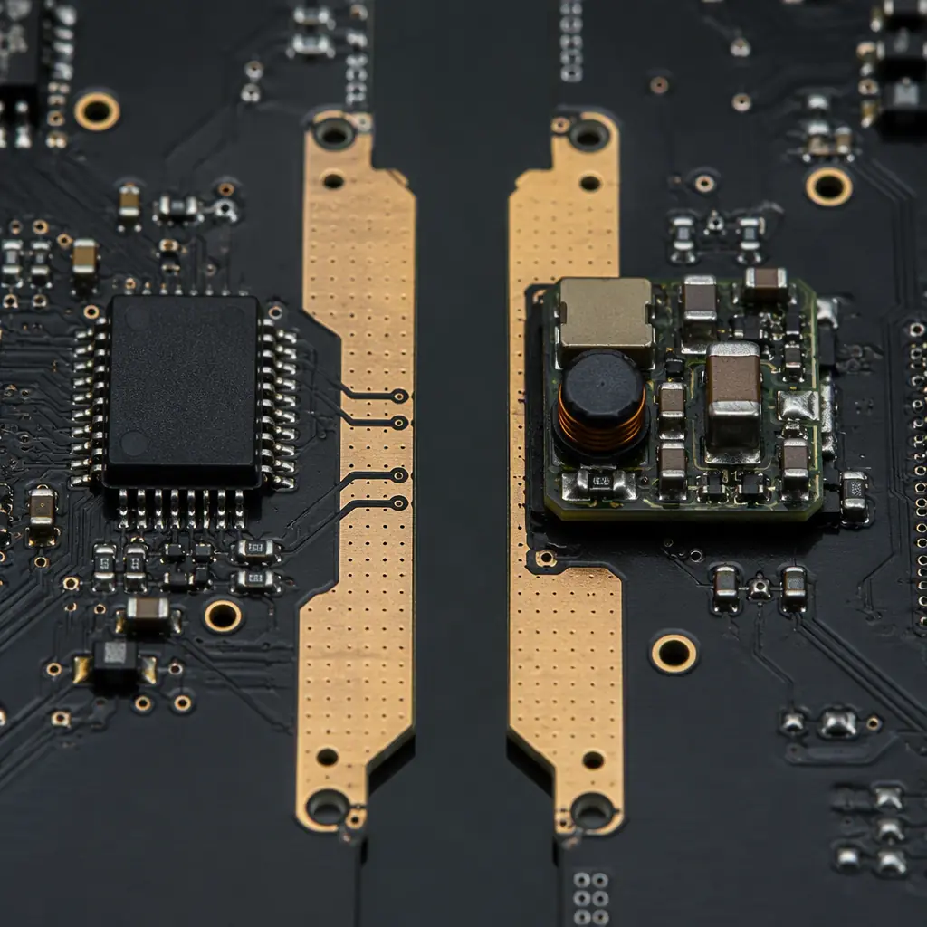
In solar inverters, EV chargers, medical devices, and anything where the cable's ground potential differs from the board's, RS-485 needs galvanic isolation: the transceiver side floats on its own isolated power, communicating with the MCU through a digital isolator. This is the definitive fix for ground-loop noise and the reason most professional industrial interfaces are isolated.
Use a Digital Isolator Plus an Isolated DC-DC, or an Integrated Isolated Transceiver
The classic approach: a digital isolator (ISO7721 or similar) between the MCU UART and the transceiver, with an isolated DC-DC (or a transformer-based solution) powering the bus side. Integrated parts (e.g. isolated RS-485 transceivers) combine both in one package. Either way, the layout must respect the isolation barrier, no traces crossing the gap except the isolation-approved paths.
Keep the Isolation Barrier Clean, No Copper, No Traces, No Solder Bridges
Cut the ground plane under the isolator and keep at least the manufacturer-specified creepage (typically 8 mm for reinforced isolation per IEC 62368-1) between the primary and secondary domains. The PCB house must not auto-stitch the two grounds with thermal vias, flag the isolation barrier in your fabrication notes. A bridged barrier turns an isolated design into a non-isolated one with extra components.
Test Isolation Voltage as a Production Step
Isolation is a manufactured property, it must be verified. Add a hipot (dielectric withstand) test to the production test plan, typically 1–2.5 kV for a few seconds between the isolated bus side and the logic side. Our PCB testing guide covers how isolation tests fit into the broader test strategy alongside flying probe and functional test.
Key Takeaway: If your product talks to the outside world over a cable, ask one question first: is the bus side galvanically isolated from the logic side? Isolated RS-485 with proper creepage and a hipot test eliminates the entire class of ground-loop field failures.
Connectors, Cabling and System Integration
The connector is the weakest mechanical and electrical link in any industrial interface. Its choice affects EMC, field service, and long-term reliability.
Choose Screw-Terminal or Pluggable Connectors With Clear A/B Labeling
For Modbus/RS-485 field wiring, pluggable screw terminals (5.08 mm pitch) are the industry standard, they accept solid and stranded wire and survive vibration. Label the pins A, B (and GND/SHLD) on silkscreen next to the connector; wiring polarity mistakes are the most common RS-485 installation error. For daisy-chained devices, provide two connector positions (IN/OUT) or a single connector with the network continuing through the termination footprint.
Ground the Cable Shield at One End Only
Shielded twisted pair should have its shield connected to earth/chassis ground at one end (usually the master or the panel entry) to avoid ground loops. On the PCB, provide a shield/ground pad near the connector, and document the recommended wiring in the manual. The board cannot enforce correct field grounding, but it can make it easy.
Leave Room for Service: Status LEDs and a Test Header
An RS-485 activity LED (driven by the MCU, not raw bus data) and a small test header for bus monitoring save enormous field time. The LED driver and its resistor belong near the MCU, not near the transceiver, to keep the indicator wiring away from the differential pair.
Manufacturing and Test Checks for Serial Interfaces
Serial interface boards fail in the field for two reasons: protection components not populated (cost-down) and isolation not verified. Both are caught at manufacturing if the test plan requires it.
Verify the Protection Network Is Populated and Oriented
TVS diodes are unidirectional or bidirectional, a mis-oriented unidirectional TVS shorts the line. AOI catches most, but a loop-back continuity test on the A/B lines with protection populated verifies the network electrically. Specify "protection populated on all units" in the BOM and assembly instructions; a "cost-reduced" unit without TVS will fail its first ESD event.
Run a Loop-Back and Multi-Node Functional Test
The production test should include: (a) a UART loop-back test through the transceiver to verify TX/RX paths, (b) a two-node test with a known-good partner at the maximum baud rate to verify timing, and (c) for isolated boards, the hipot test described above. A serial port that passes loop-back but fails with a partner usually has a termination or bias fault, exactly what the two-node test catches.
Document the Interface in the Product Manual
Baud rate, parity, termination requirements, fail-safe biasing, shield grounding, and the wiring diagram belong in the manual shipped with the product. Field failures of RS-485 networks are almost always installation errors, clear documentation is the cheapest reliability improvement available.
Summary: The Industrial Serial Interface Checklist
A field-reliable RS-485/RS-232 interface is: correctly terminated at both cable ends with 120 Ω and fail-safe biased; protected in the right order (choke → TVS → transceiver) with protection ground kept out of the logic ground; laid out with the transceiver near the connector and the A/B pair tight over a solid ground; isolated when the bus ground is not your ground, with a clean creepage barrier and a hipot test; and documented so installers cannot wire it wrong. None of this is expensive. It is all decided at layout time, which is exactly when it belongs.
At Huaxing PCBA we manufacture industrial control and IoT boards with RS-485/RS-232 interfaces up to 32 layers, including isolated designs with verified creepage and hipot testing, surge-protected front-ends, and loop-back plus two-node functional test on every unit. Our DFM review checks your termination network, protection ordering, isolation barrier, and connector placement before tooling. Read our industrial control PCB guide for the system-level view, or send your interface files for a free DFM review and quote.
