
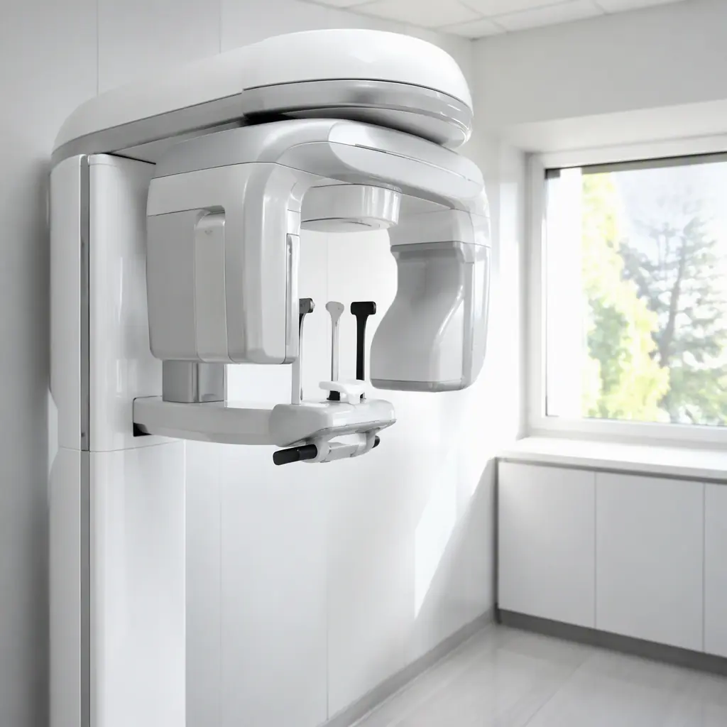
Dental equipment is a demanding niche of medical electronics. A CBCT machine generates and detects X-rays with sub-millimeter precision while a patient sits 30 cm away; an intraoral scanner captures 3D geometry at hundreds of frames per second inside a mouth; a curing light must deliver a precise light dose to polymerize resin. And every one of these devices is used daily, in a clinic, by staff who are not electronics engineers. The PCBs inside them have to satisfy IEC 60601 safety, ISO 13485 quality systems and, increasingly, cybersecurity requirements for networked imaging.
This guide breaks down the PCB requirements across the main dental device families, the manufacturing and compliance considerations OEMs must plan for, and how to specify boards that pass certification the first time. Huaxing PCBA manufactures and assembles medical-grade PCBs for dental and diagnostic equipment under ISO 13485 and IPC Class 3 processes. This is the guidance our engineers apply to every medical order.
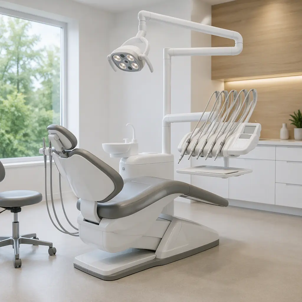
The Dental Device Families and Their PCB Needs
Dental equipment spans a wide range of electronics, from high-voltage imaging to battery-powered handhelds. Each family has different PCB priorities.
| Device Family | Electronics Content | PCB Priority |
|---|---|---|
| CBCT / panoramic X-ray | X-ray generator, flat-panel detector, motion control | High-voltage, high-speed data, shielding |
| Intraoral scanners | Camera module, structured light, FPGA processing | Miniaturization, low noise, thermal |
| LED curing lights | Blue LED driver, battery management, dose control | Thermal, constant-current accuracy |
| Dental chairs / units | Motor drives, foot pedal, touch controls, memory | EMC, reliability, cable harness |
| Handpieces / scalers | Micro-motor, ultrasonic transducer, control loop | Vibration tolerance, small form factor |
For a device OEM, the common thread is regulatory: every board that touches the patient or mains power falls under IEC 60601-1, and imaging devices add the specific standards for their modality. The overall compliance framework, the certifications a medical PCB supplier must hold, is covered in our PCB certifications guide.
CBCT and Panoramic Imaging: High Voltage Meets High-Speed Data
A CBCT unit combines an X-ray source (typically 60–90 kV) with a flat-panel detector, all rotating around the patient's head. The PCBs involved span two very different worlds.
The high-voltage generator board
The X-ray generator board converts mains or a DC bus to the tube voltage. This is a high-voltage PCB: 60–90 kV on the tube side, which means deep creepage rules, conformal coating, and layer-to-layer spacing designed for the peak voltage. The layout rules for these boards follow our high-voltage PCB design guide . With the extra twist that the generator sits meters away from sensitive detector electronics, so shielding and filtering are mandatory.
The flat-panel detector readout
The detector is a large-format CMOS or a-Si panel read out through hundreds of parallel channels. The readout boards handle 14–16 bit analog-to-digital conversion at high speed, then serialize the data over LVDS or a fiber link to the host PC. This is a precision mixed-signal board: the analog front end needs an exceptionally clean power and ground scheme, and the digital serializer must not couple back into it. The grounding and partitioning discipline is detailed in our mixed-signal PCB design guide.
Motion control for the gantry
The gantry rotation and vertical travel are driven by servo motors with encoder feedback. These drives share the machine with the imaging chain, so their PWM noise must be contained, input filtering, shielded motor cables and a physical partition on the PCB between the drive section and the signal section. The motor-drive layout fundamentals are in our BLDC motor controller guide.
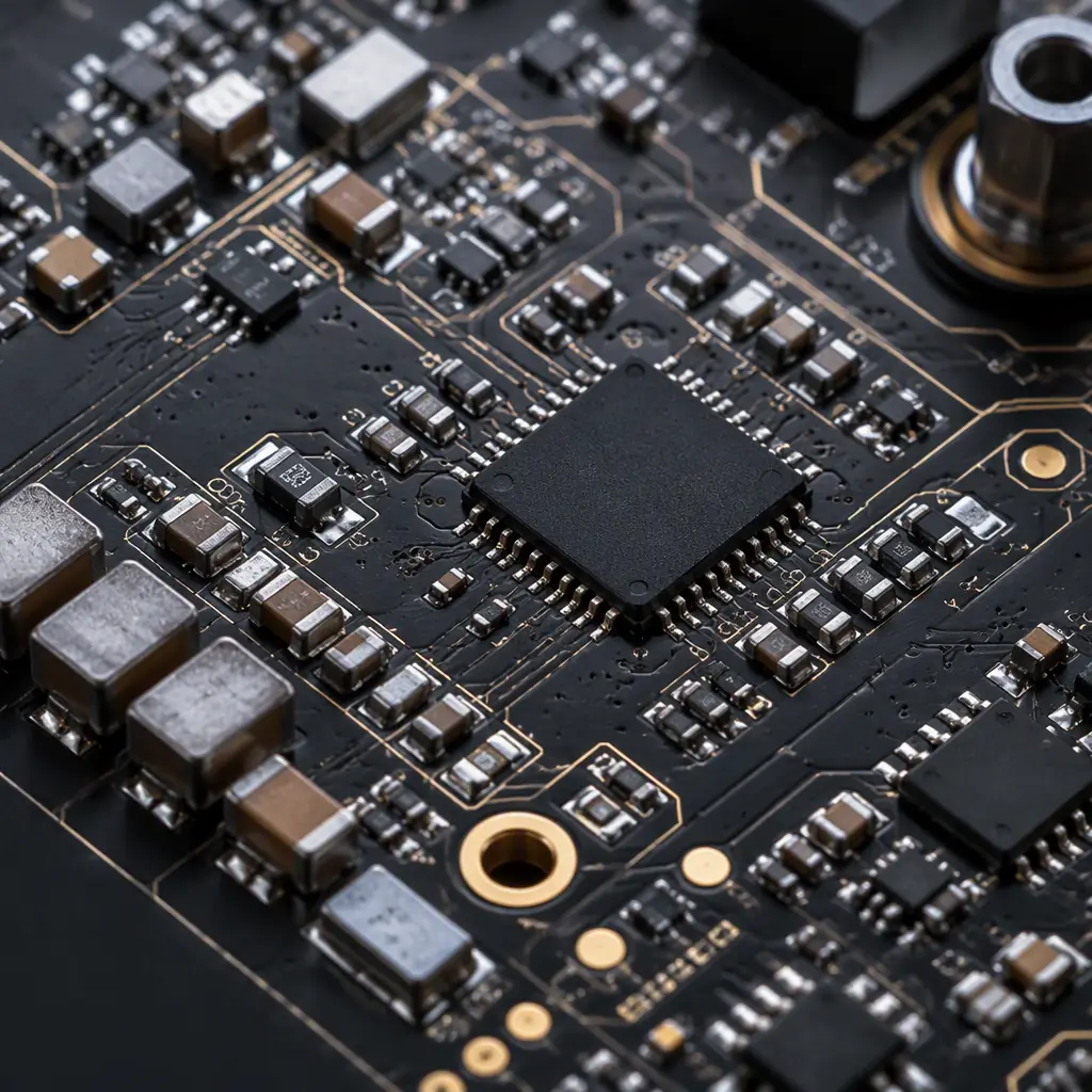
Key Takeaway: CBCT is two PCBs in one machine: a high-voltage power board and a precision imaging chain. Never let them share a ground plane without a defined, filtered reference. The generator will corrupt the detector's image quality and the certification test will catch it.
Intraoral Scanner Electronics: Small, Fast, and Low-Noise
An intraoral scanner captures a 3D model of the teeth in real time using structured light or confocal imaging. The electronics are a camera module, a projector (LED or laser), and an FPGA or SoC doing real-time 3D reconstruction, all inside a handheld wand.
Camera and sensor integration
The image sensor (typically 1–5 MP at 30–60 fps) sits on a tiny board at the wand tip, connected to the processing board over MIPI or LVDS. The sensor board is a short, carefully routed flex or rigid-flex assembly. The routing rules for MIPI camera interfaces are covered in our camera module PCB design guide.
FPGA processing and thermal management
The 3D reconstruction runs on an FPGA or SoC that draws 5–15 W inside a handheld device. That heat must move out through the wand body without making it uncomfortable to hold. The processing board needs the thermal design, planes, vias, heat spreader, described in our PCB thermal management guide, plus enough decoupling for the FPGA's switching load as covered in our FPGA PCB design guide.
Sterilization and ingress realities
The wand is disinfected between patients with wipes and sprays. The board must survive the chemicals: conformal coating on the processing board (the sensor window stays uncoated), sealed connectors, and materials rated for the clinic's disinfectant. The coating selection process is covered in our conformal coating guide.
LED Curing Lights and Handpieces: Power and Precision in Your Hand
Curing lights and electric handpieces are the highest-volume dental electronics, thousands of units, battery-powered, and used every day. Their PCB challenges are about delivering precise power in a small, warm enclosure.
| Device | Key PCB Requirement | Typical Spec |
|---|---|---|
| Curing light | Constant-current LED driver, dose control | 1–4 W optical, 385–480 nm, 10–20 s cycles |
| Electric handpiece | Micro-motor drive, speed/torque loop | DC 1.5–2 A, up to 40,000 rpm |
| Ultrasonic scaler | Transducer drive at 25–30 kHz, amplitude control | Resonant drive, feedback sensing |
| Battery (both) | Li-ion charge management, protection | 1S–2S, CC-CV charging |
The curing light is the stricter design: the LED must deliver a consistent irradiance (typically 1000–2000 mW/cm²) over the curing window, so the constant-current driver needs tight regulation and the thermal path must keep the LED from derating mid-cycle. A 2 W optical LED dissipates 3–6 W of heat in a handheld body. The LED board is usually an aluminum-core or ceramic board for exactly this reason, as covered in our metal core PCB guide. Handpiece and scaler drives are motor-control problems; the drive layout rules are in our BLDC controller guide, and the battery management follows our portable power station BMS guide at smaller scale.
Dental Chairs and Units: EMC and Reliability Under Daily Use
The dental chair is the least glamorous board in the clinic and the one that must never fail mid-procedure. It contains multiple motor drives (lift, backrest, headrest), foot-pedal controls, position memory, and often an integrated light and monitor arm.
Motor drives and position memory
Chair motors run on 24 V DC with current peaks of several amps; the control board combines the drive stages with a microcontroller, position encoders and a non-volatile memory for preset positions. The mixed power/logic board needs careful partitioning and the EMC measures from our EMI/EMC design guide . A chair shares a circuit with imaging equipment in many clinics.
Foot pedal and hand control interfaces
The foot pedal and delivery unit controls are connected over long cables running through the chair base. These interfaces need robust ESD protection and filtered inputs. A static discharge from a clinician's shoes traveling up the foot pedal cable is a classic chair failure. ESD protection design follows our ESD control guide.
Reliability over a decade of daily use
Clinic equipment is expected to last 7–10 years in daily service. That means conservative component derating, robust solder joints (Class 3 assembly), and connectors rated for the mechanical cycles of the harness. The acceptance and inspection criteria that govern this are covered in our IPC-A-610 acceptance guide.
Compliance: IEC 60601, ISO 13485 and the Paper Trail
Dental electronics are medical devices. The PCB supplier's job is to make certification achievable, not to certify the device. But the supplier's processes and documentation are part of the OEM's audit trail.
- IEC 60601-1 . The base safety standard for all medical electrical equipment: creepage/clearance, patient leakage, EMC (IEC 60601-1-2). Boards must be manufacturable to the isolation distances the standard demands.
- Modality standards, CBCT falls under IEC 60601-2-63 (dental extra-oral X-ray); scanners and other devices may add IEC 62304 for software and IEC 62471 for optical safety.
- ISO 13485 . The quality system; the OEM's certification audit examines supplier controls, traceability and change management. The manufacturing requirements are covered in our medical device PCB guide.
- Cybersecurity . Networked imaging devices fall under FDA/EU MDR cybersecurity expectations; the PCB supports this via secure boot storage, hardware roots of trust and traceable firmware regions.
The practical consequence: specify IPC Class 3, require full lot traceability, demand the supplier's ISO 13485 certificate and change-notification process, and lock the materials (laminate, solder mask, finish) in the documentation. Material changes after certification require re-validation, a disciplined supplier prevents that surprise. The documentation and audit requirements are detailed in our lot traceability guide.
Summary: The Dental PCB Specification Checklist
When you spec PCBs for a dental device, pin down ten things: device family and its modality standard; IEC 60601-1 isolation requirements and creepage; IPC Class 3 assembly and inspection; ISO 13485 supplier certification and traceability; conformal coating for the disinfectant environment; thermal design for handheld power devices; low-noise partitioning for imaging chains; ESD protection on all external cable interfaces; locked materials with change notification; and a test protocol (AOI, X-ray, functional, burn-in) matched to the device's risk class. Dental devices are used on people, every day, by non-engineers, the boards inside them carry the same weight as any implantable.
Huaxing PCBA manufactures and assembles medical-grade PCBs for dental and diagnostic OEMs under ISO 13485, IPC Class 3, with full lot traceability and RoHS/REACH compliance. Read our medical imaging PCB guide for the imaging-specific deep dive, or send our engineering team your dental device design for a free DFM and compliance review within 24 hours.
