
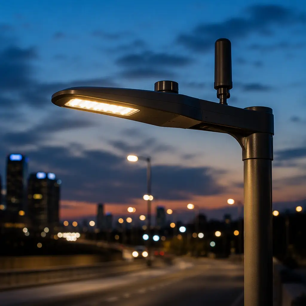
Street and roadway lighting is one of the largest single categories of outdoor power electronics, driven by the switch from high-pressure sodium to LED and by the push to make city lighting smart and energy-efficient. A municipal roadway fixture is a small power converter and controller mounted on a pole in the weather, exposed to lightning, high summer heat, winter cold, salt, dust and insects for a decade or more. The controller board that powers and dims the LED array has to be engineered for that reality. At Huaxing PCBA we build these outdoor lighting driver and control boards with 8 SMT lines, 0.3 mm pitch, 0201 placement and 32-layer fabrication, in 15,000 m² serving 30+ countries.
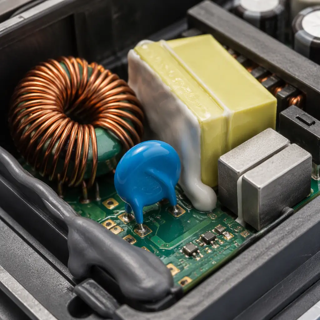
Outdoor Lighting Is a Power and Survivability Problem
An indoor LED driver has a predictable, clean environment and a low line voltage. An outdoor roadway fixture operates at a higher line voltage, faces surges and lightning, must hold an acceptable power factor for the utility grid, and has to shed heat from a sealed enclosure that sits outside all day in direct sun. These are the four things that separate an outdoor fixture controller from an indoor one, and they shape the board design more than the dimming protocol ever will.
| Characteristic | Indoor driver | Outdoor street fixture |
|---|---|---|
| Line voltage | 120/240V | 120/277/347/480V |
| Surge exposure | Low, conditioned | Up to 10kV lightning |
| Enclosure | Ventilated, benign | Sealed IP66/67, harsh |
| Thermal | Mild, convective | Direct sun, sealed, high heat |
| Service life | 3–5 years | 10+ years expected |
High-Line Voltage Input: 277V, 347V, 480V and Power Factor
In North America, commercial and municipal lighting often runs on a 480V/277V three-phase feed, where the phase-to-neutral voltage is 277V. Street and parking-lot lighting commonly uses these higher line voltages, which means the converter has to be designed for a wide input range, from 120V up to 480V . And still deliver a regulated drive to the LED string.
Wide-input power conversion
A universal-input design that works from 120V to 480V is harder than one fixed at a single voltage. The front-end has to handle the voltage range without over-stressing the capacitors and switches, and the keep-out and creepage distances have to be sized for the highest input. This is a real design trade-off in board area and BOM cost. Our power electronics PCB and high-voltage PCB design guides cover the clearance and insulation requirements.
Power factor correction
Utilities impose power factor requirements on large lighting installations, and street lighting is a big aggregated load. A good outdoor driver holds a power factor above 0.95 and low total harmonic distortion, which requires active PFC, that adds a boost-stage component set and a switching controller. The PFC stage and the LED drive stage interact, so the design has to be well-integrated. See our SMPS layout and LED PCB manufacturing guides.
Creepage and clearance for high voltage
At 480V, the clearance and creepage between live parts and the rest of the board have to accommodate the higher stress, and the isolation between the AC input and the low-voltage control has to be adequate. A crowded board that meets clearance for 240V may not meet it for 480V, so the spacing has to be designed in from the start.
Lightning and Surge: Protecting the Controller
A roadside fixture is one of the most surge-exposed electronics around. A nearby lightning strike can inject a transient of many kilovolts onto the power lines, and the controller has to survive it and keep working. This is why outdoor fixtures are tested to surge standards like IEEE C62.41 and IEC 61000-4-5, with combinational waves and ratings like 10kV / 10kA.
Surge protection stages
Surge protection is layered: a MOV or gas tube at the AC input clamps the high-energy strike, then a series impedance and a TVS or varistor at the input of the converter handle what remains. A single part is rarely enough. The board has to place these components so that the energy path is safe and does not produce an arc. Our ESD control and EMC/EMI compliance guides cover protection design.
Surge testing and co-ordination
The protection has to co-ordinate: the first stage clamps before the second sees too much, and the second stage protects the electronics before they fail. A design that tests a single component in isolation can fail in the system. The board has to be validated to the actual surge level of the installation, not just a datasheet rating. Our testing methods guide covers the validation approach.
Grounding and layout
The surge energy has to go somewhere safe, so the grounding and the return path matter. A poor layout can route the transient through sensitive logic rather than to ground. The board needs a dedicated, low-impedance surge return path and a clean separation between the AC front-end and the low-voltage control.
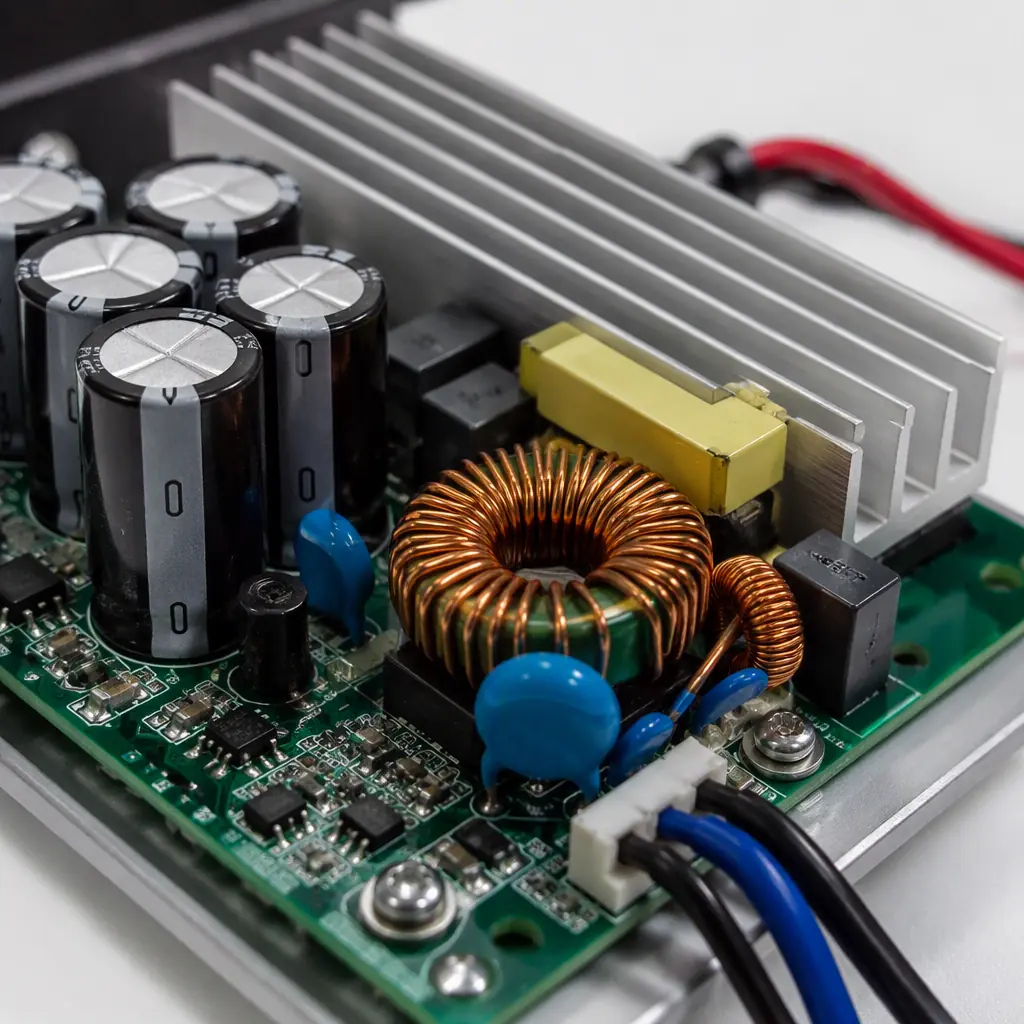
Smart Pole: Photocell, Dimming and Remote Telemetry
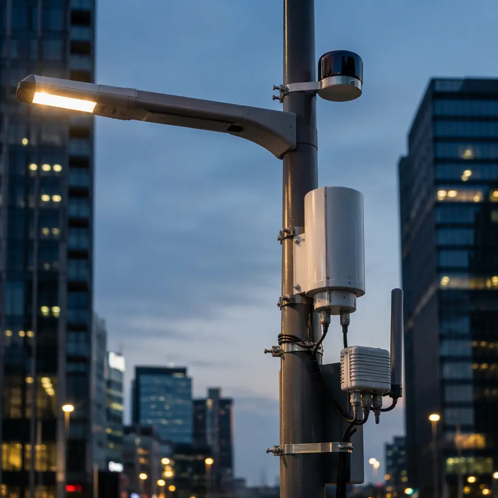
Modern street lighting is smart. A fixture typically includes a photocell that turns the light on at dusk, a dimming interface so it can be throttled for energy savings, and increasingly a radio link (DALI-2, Zigbee, LoRaWAN or NB-IoT) that lets the city monitor and control every lamp remotely. The controller board is where all of this comes together.
Photocell and NEMA receptacle
Most North American poles use a NEMA 7-pin receptacle (ANSI C136.41) that accepts a photocontrol and now supports dimming and communication. The board has to provide that proper receptacle, detect the ambient light and drive the dimming signal. The mechanical and electrical interface is as important as the electronics. Our smart lighting driver guide covers the dimming and control protocols.
Dimming and communication
Dimming is used to cut energy at off-peak hours, to dim in response to a sensor, or to implement adaptive lighting. The interface is usually 0-10V or a digital protocol like DALI-2. Remote telemetry over LoRaWAN or NB-IoT lets the city detect a failed lamp, dim a whole zone, and log energy use. Our BLE, LoRaWAN and cellular IoT guides cover the RF side.
RF coexistence on a power board
Putting a radio on a board that switches kilowatts is a coexistence challenge. The switching stage generates noise that can desensitize the radio, and the radio's antenna has to be placed so it does not couple into the power section. The layout has to separate the RF from the power, filter the supply, and keep the antenna clear. This is a board-level skill that directly affects whether the smart pole works.
Thermal and Sealed-Enclosure Design
An outdoor fixture is a sealed box in direct sun. The LED array generates heat, the driver electronics generate heat, and the enclosure has little way to get rid of it. The controller board has to be designed to run hot, and the LED junction temperature has to stay low enough to maintain light output and long life. This is where board-level thermal design is non-negotiable.
High-temperature design and derating
The board has to be designed for an ambient that can reach >50°C in the sun, with the electronics derated for the real operating temperature. Component selection, copper weight and thermal vias all come into play. A board that passes testing at 25°C but is mounted on a pole at 60°C will fail in the field. Our thermal management and copper weight selection guides are the reference.
Sealed enclosure and potting
The enclosure has to be sealed to an IP rating, and the electronics inside may be conformal-coated or potted to resist moisture, salt and insects. A sealed box traps heat, so the thermal design has to work within that constraint. Our conformal coating and potting & encapsulation guides cover the protection options.
Corrosion and thermal cycling
Outdoor fixtures cycle through heat and cold, and thermal cycling plus moisture can cause corrosion and solder-joint fatigue. The board has to use materials and a layout that tolerate this, with proper finish selection and thermal expansion management. The result is a service life measured in years, not months.
Procurement Tip: Ask the supplier to show the thermal simulation or the hot-box test data, and the surge test report, not just the bill of materials. A street fixture that survives a storm and still meets its power factor and light output a decade later is the design achievement; one that only looks correct on paper is a maintenance liability for the city.
What to Specify With a Street-Lighting PCBA Supplier
Outdoor lighting controllers are bought on reliability, grid compliance and longevity, not on a headline efficiency figure. The checklist below is the practical minimum when you source an outdoor fixture controller.
| Specification | What to demand | Why it matters |
|---|---|---|
| Input range | 120–480V, wide range | Covers municipal/their feeds |
| Power factor | >0.95, low THD | Grid compliance and energy |
| Surge | 10kV / 10kA, tested | Survives lightning, keeps working |
| Thermal | >50°C ambient, derated | Sealed box in direct sun |
| Protection | IP rating, conformal/potting | Sealed against moisture, salt |
At Huaxing PCBA we build outdoor lighting driver and control boards with 8 SMT lines, 4 DIP lines, 32-layer fabrication and 0201 / 0.3 mm pitch placement, in a 15,000 m² facility with 500+ staff serving 30+ countries. We are ISO 9001, IATF 16949 and UL (E354321) certified, with a 99.2% on-time delivery and 98.7% first-pass yield. Upload your design for a quote or talk to our engineering team about your street-lighting project. For related applications, see our LED PCB manufacturing and new energy guides.
