
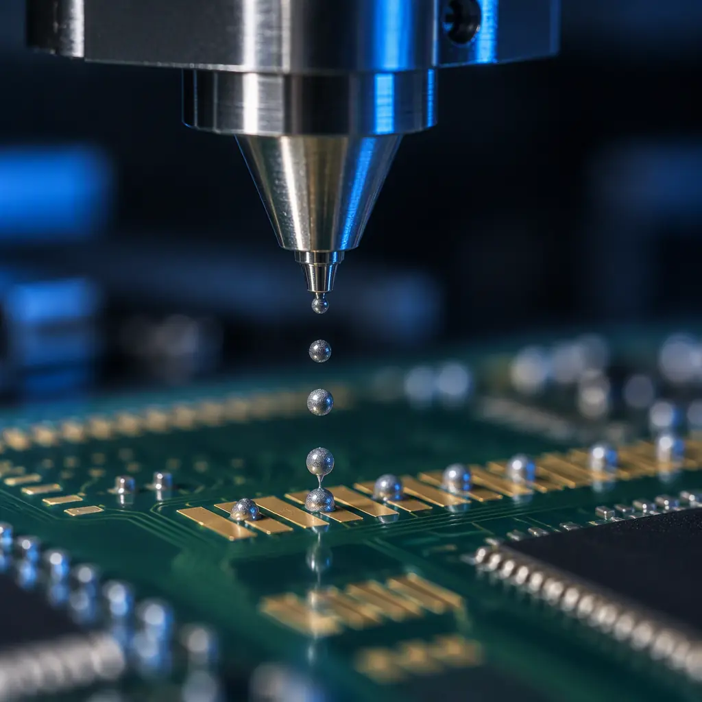
Solder paste jetting has moved from a niche NPI tool into a genuine production option. Where a programme runs many short builds, where a design changes every few weeks, or where a stencil's eight to fourteen day fabrication lead time is the critical path, depositing paste from a piezoelectric valve instead of through a foil aperture is an obvious operational win. The tooling cost disappears, the changeover collapses to a file change, and the line can run a different board every shift.
What does not disappear is the burden of proof. A stencil is a fixed geometric object; its aperture defines the deposit and the deposit is therefore repeatable by construction. A jetting valve defines the deposit through a dynamic balance of nozzle geometry, pressure, valve open-time, substrate motion, paste rheology and standoff height. That means the process window is real, the interactions matter, and the capability has to be demonstrated rather than assumed. A jetter that produces a convincing demonstration board is not the same thing as a qualified process, and the difference is entirely in the evidence.
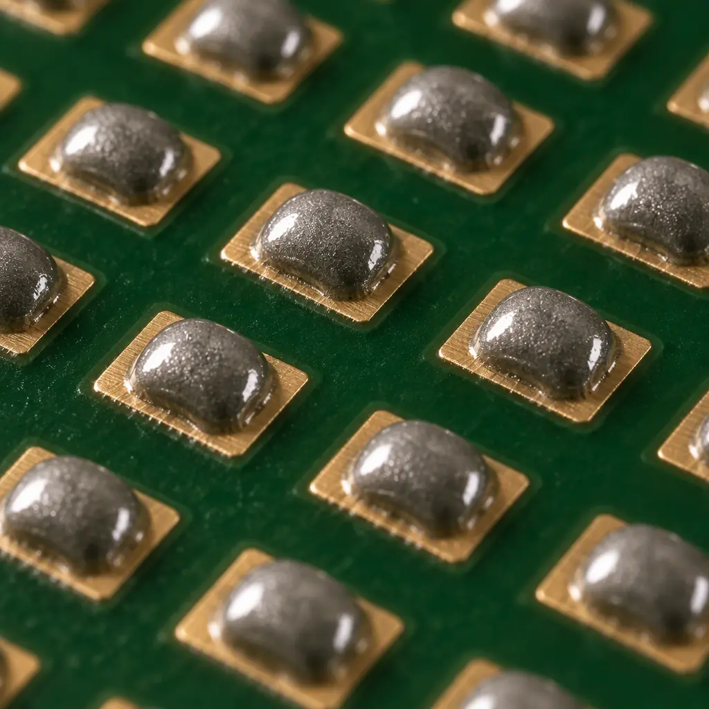
What Changes When the Stencil Disappears
The engineering consequence of removing the stencil is that several quantities that were formerly set by geometry become process variables. Understanding which ones is the first step in building a qualification plan.
| Parameter | Stencil Printing | Jetting |
|---|---|---|
| Deposit volume | Set by aperture area and foil thickness | Set by droplet volume, droplet count and flight dynamics; must be verified per aperture class |
| Deposit height and area | Emerges from aperture geometry and paste release | Emerges from droplet spreading on the pad; sensitive to pad finish and paste rheology |
| Paste volume as a function of pad | Linear in aperture area | Quantised in droplet increments; fine pads may receive few droplets and show higher relative variance |
| Aperture-area ratio limit | Governs the smallest printable feature | Replaced by a minimum reliable droplet volume and placement accuracy limit |
| Changeover time | Stencil change plus paste handling | Software change; minutes |
| Paste types usable | Broad, but release limits fine-pitch options | Rheology-limited; not every paste jets reliably |
The quantisation point is the one buyers most often miss. A stencil delivers a continuous volume proportional to aperture area, so a small pad and a large pad scale smoothly. A jetter delivers an integer number of droplets, and if a fine-pitch pad nominally receives two droplets while a nearby pad receives six, the relative variance on the two-droplet pad is inherently higher. That does not make the process unacceptable, but it does mean the capability statement has to be made per aperture class rather than as a single number for the board. How that variance translates into joint quality is the same question the SPI process controls for stencil printing, covered in solder paste volume control and SPI.
Key Takeaway: Ask for capability data broken out by aperture class, not a single board-level number. A jetting process that holds 3 percent volume repeatability on 0402 pads and 12 percent on 01005 pads is a usable process if the fine-pitch class is understood and controlled — but a supplier quoting one global figure is not measuring the thing that matters.
Step 1 — Establish Droplet-Level Capability First
Qualification should start at the smallest unit the process produces, which is a single droplet, and work upward. Skipping this step is the most common cause of a programme that passes a demo and then struggles in production.
Droplet characterisation means measuring volume and mass repeatability from the valve itself, on a defined paste, over a run long enough to be meaningful — typically several thousand consecutive shots with the data logged, not a sample of twenty. What you are looking for is the coefficient of variation of droplet volume and its drift over the run, because drift is what degrades into a defect three hours into a shift.
Droplet volume and repeatability
Measure the mean droplet volume and its standard deviation at the intended operating parameters. A jetting valve is typically capable of a nominal droplet in the low nanolitre to sub-nanolitre range depending on nozzle size, controlled by valve open time and pressure. What matters for production is not the smallest achievable droplet but the repeatability at the droplet size the board actually needs. Report the coefficient of variation over a continuous run.
Drift over a production-length run
Run the valve continuously for a period representative of a shift, replenishing paste as the production process would, and plot droplet volume against time. A process that is stable for the first ten minutes and drifts by 8 percent at the two-hour mark is not qualified; it is a process that will produce a rising defect rate across a shift. A hot-melt or temperature-controlled valve stabilises much faster than an ambient one, which is a genuine specification difference rather than a marketing claim.
Placement accuracy and its effect on the deposit
Droplet landing position matters because a droplet that lands partly off the pad loses paste to the solder mask and changes the effective deposit area. Characterise the placement capability against the smallest pad in the design and confirm that the resulting deposit, not the nominal placement figure, still meets the volume target. This is the step where a system's headline accuracy specification and its practical capability on your board diverge.
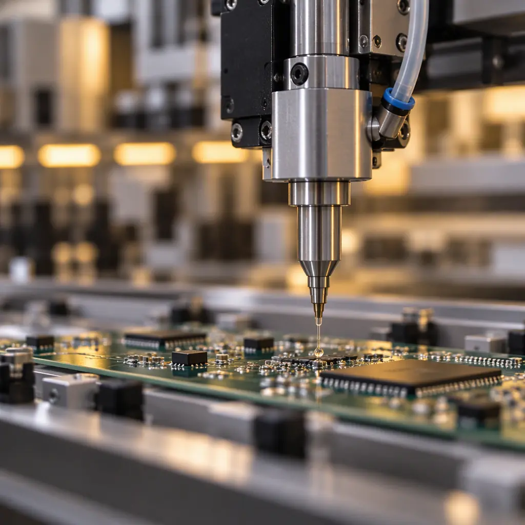
Step 2 — Design of Experiments on the Interacting Parameters
Jetting parameters interact, which is exactly why a one-factor-at-a-time tuning approach produces a process that looks optimal in isolation and fails in combination. A properly designed experiment on the four dominant factors will tell a programme more in a week than months of incremental adjustment.
The four factors worth studying are nozzle size, valve open time, paste pressure and standoff height between nozzle and substrate. Paste temperature belongs in the design as well where the valve is temperature-controlled, because it controls viscosity and therefore droplet formation. A fractional factorial design at two or three levels per factor is normally sufficient to identify the significant main effects and the dominant interactions; the objective of the experiment is not to build a precise response surface but to find the region where the process is robust to perturbation.
| Factor | Effect on Deposit | Interaction to Watch |
|---|---|---|
| Nozzle diameter | Sets the droplet size range and the minimum reliable volume | Interacts strongly with paste particle size; a nozzle too small for the paste fraction will clog intermittently |
| Valve open time | Primary control of droplet volume | Interacts with pressure; the same volume can be reached by several combinations with different stability |
| Paste pressure | Affects droplet formation consistency and refill of the chamber | Interacts with paste viscosity and therefore with temperature and time since stirring |
| Standoff height | Changes droplet shape on landing and the risk of satellite droplets | Interacts with substrate flatness; warpage across a large panel changes effective standoff locally |
| Paste temperature | Controls viscosity and therefore jetting behaviour | Interacts with everything; unheated lines drift with ambient |
The deliverable from this step is not a single set of setpoints but a robustness statement: how far each factor can move from nominal before deposit volume leaves specification. That is the difference between a process that survives a hot afternoon in the factory and one that requires the room to be held at exactly the condition it was tuned in. A process whose volume moves more than a few percent when standoff changes by a tenth of a millimetre is a fragile process, and the fragility is a specification finding rather than a maintenance issue.
Step 3 — Capability on the Real Board, Not a Test Vehicle
Capability has to be demonstrated on the production design in its production panel, because both the aperture classes and the thermal mass of the panel affect the outcome. Two board-level families of measurement matter, and both should be reported as process capability rather than as a mean.
Paste deposit volume, area and height by SPI
Run SPI on every board of the qualification lot and analyse the data by aperture class. Report mean, standard deviation and the capability index against the paste volume tolerance the assembly requires. A common production target is a capability index of at least 1.33 on volume for the dominant aperture class, with the fine-pitch class reported separately even where it is lower, because hiding a weak class inside a good average is the failure mode to avoid.
Resulting joint quality after reflow
Deposit volume is a proxy. The real acceptance is the reflowed joint: open joints, insufficient solder, bridging, solder balling and, for area-array packages, voiding measured by X-ray. The qualification lot should be inspected to the same acceptance criteria the programme will use in production, and the defects found should be traceable back to specific deposit outliers where possible. How those criteria are set is covered in IPC-A-610 acceptance criteria.
If the board carries area-array packages with exposed pads, add the package-specific checks: paste release from a jetter behaves differently from stencil release over a large continuous pad, and the void behaviour of a QFN or LGA made by jetting deserves its own verification. The specific acceptance limits are set out in our guide to QFN and LGA leadless package soldering.
Ongoing Control After Qualification
A qualified process that is not monitored decays. Because jetting parameters drift and paste properties change with time and temperature, the control plan has to include ongoing measurement rather than relying on the qualification record.
| Control Element | Frequency | Rationale |
|---|---|---|
| Droplet mass verification on a test substrate | Start of each build or shift | Detects valve drift, nozzle partial clog and paste batch change before boards are produced |
| SPI on the first board of the build | Every build | Confirms the deposit matches the qualified profile on the actual design |
| Nozzle inspection and cleaning | Per defined interval or measured droplet count | Prevents the intermittent clog that produces a single missing deposit in an otherwise good board |
| Paste age and temperature log | Continuous | Jetting is far more sensitive to paste condition than stencil printing; an expired or over-warmed paste jets differently |
| Post-reflow joint inspection | Per sampling plan | Confirms the deposit-to-joint correlation still holds after any change to paste or parameters |
Statistical process control on the deposit volume is the mechanism that makes this real rather than documentary. A control chart on droplet mass with a defined reaction plan catches drift before it produces defects, and it is the evidence that turns a qualification certificate into an operating discipline. The statistical framework and the capability targets appropriate for PCBA processes are set out in our guide to SPC and Cpk for PCBA.
Procurement Tip: Ask three questions before accepting jetting on a production programme. First, show me the droplet-mass control chart for the last month, not the qualification report. Second, what is the capability index on paste volume for the fine-pitch aperture class specifically, not for the board as a whole? Third, what is the nozzle cleaning interval and what triggers an unplanned clean? A supplier who can answer the first question from live data has a controlled process. One who can only produce a qualification document has a process that was qualified once and may not be running that way now.
Where Jetting Wins and Where It Does Not
Qualification effort is only worth spending where the process fits the programme. Jetting earns its place on high-mix, low-to-mid volume work, on NPI where tooling lead time dominates the schedule, and on programmes where the design changes often enough that stencil revisions would be a recurring cost and delay. It is a strong fit for prototype and pilot builds that must produce electrically representative boards quickly. The economic comparison against tooling is set out in zero-tooling SMT stencils and the break-even calculation in stencil-free SMT for NPI.
It is a poorer fit where a single high-volume design will run for years with no change. There, the stencil's fixed geometry is an asset: it is repeatable by construction, it does not drift, and its process window is wider for challenging aperture geometries. A stable, long-running, high-volume programme is better served by a good stencil and a well-controlled printer, and moving it to jetting would trade a low-risk process for a higher-maintenance one without an operational reason.
There is also an aperture-limit consideration. Jetting does not remove all fine-feature limits; it replaces the stencil's area-ratio constraint with a droplet-volume and placement-accuracy constraint. For the very finest pitch and smallest pads, the question is whether the jetter can put a reliable number of droplets on the pad with acceptable relative variance, and for some geometries the answer is no. Establishing where that boundary falls for your design is precisely what the capability work in step one produces, and it should be done before the process is committed to production rather than after.
The Bottom Line
Jetting is a real production process with a real qualification burden. The burden is manageable and it is finite: droplet capability first, a designed experiment on the interacting parameters second, board-level capability by aperture class third, and a control plan with SPC on deposit volume thereafter. A supplier who presents that evidence has demonstrated an understanding of their own process and can defend the deposition decision on data. A supplier who presents only a demonstration board has shown that the machine works, which is a different and much weaker claim.
At Huaxing PCBA we run jetting for NPI and high-mix production alongside conventional stencil printing, characterise droplet capability and drift before committing a programme, report paste volume capability by aperture class from SPI data, and hold nozzle cleaning and paste-conditioning on a logged interval. Read our jetting versus stencil comparison or contact our process engineering team to discuss which deposition method fits your build profile.
