
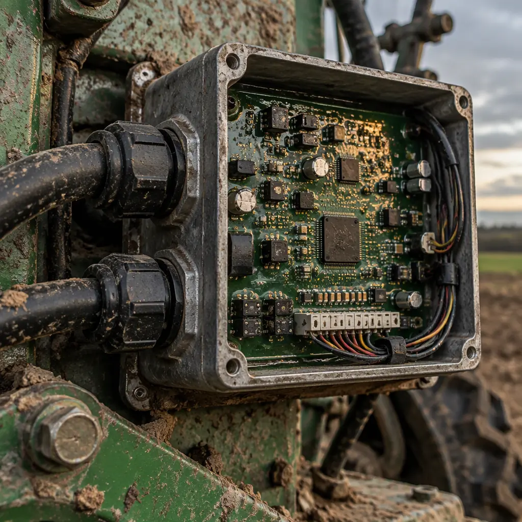
An agricultural control board lives a harder life than most industrial electronics. It is mounted on machinery that vibrates continuously, sits outdoors through a full temperature swing from a frozen pre-dawn start to a sun-exposed afternoon, is washed down with a pressure hose, and shares a 12V or 24V harness with alternators, starter motors and hydraulic solenoids that produce transients measured in hundreds of volts. Field failure rates on farm electronics are dominated by moisture ingress, power transients and connector fatigue, in that order, and none of those three are addressed by choosing faster processors or better firmware.
This page covers the board-level and enclosure-level measures that change field reliability, in the order they should be designed. For the application context and control architecture, see our agricultural electronics PCB design guide; for panel-level ruggedness on machinery, our agricultural machinery PCBA guide covers the assembly side.
Moisture And Condensation: The First Failure Mode
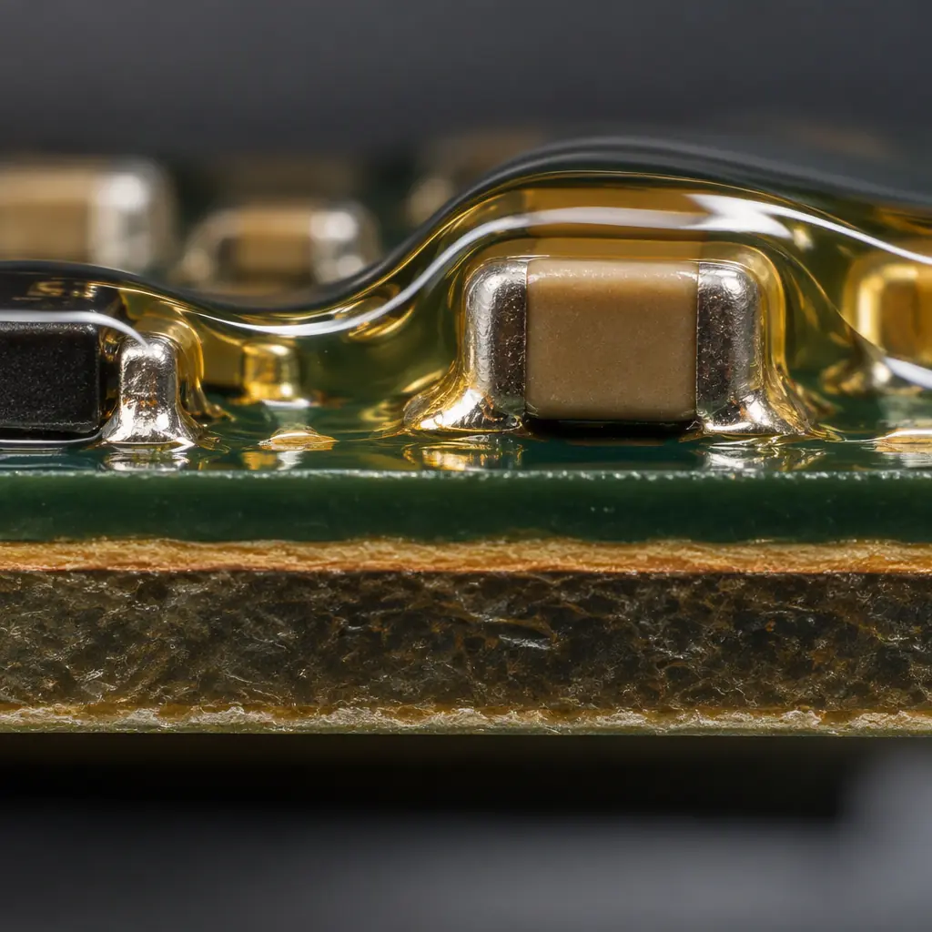
Condensation, not rain, is what damages most field electronics. A sealed enclosure that heats during the day and cools overnight draws moist air in through any imperfect seal or cable gland, and that moisture then condenses directly onto the coldest surface, which is usually the board. The result is electrochemical migration between fine-pitch traces, leakage currents that corrupt sensor readings, and eventually corrosion of solder joints.
Seal the enclosure, then protect the board anyway
Achieve an IP67 or IP6K9K enclosure with a proper gasket groove, a rated cable gland per entry, and either a breathable membrane vent or a desiccant pack. Then coat the board regardless: seals degrade, glands are re-terminated in the field, and a coated board survives a compromised seal. Treat the coating as the second line of defence, never the first.
Choose coating by chemical exposure, not by habit
Acrylic is cheapest and easiest to rework but swells with solvents and is the weakest against fuel and oil. Polyurethane holds up well against hydraulic fluid and abrasion. Parylene is the strongest barrier per micron and the best choice where condensation is continuous, but it is expensive and needs masking for connectors. Our coating types comparison and parylene guide set out the trade-offs; the thickness control guide covers how to specify and verify the film you paid for.
Clean before you coat, or you seal in the failure
Coating over ionic residue from flux traps contaminants against the board and accelerates the corrosion the coating was meant to prevent. Specify ionic cleanliness testing with an actual limit, typically under 1.56 µg NaCl equivalent per cm² for a coated assembly. Our ionic cleanliness testing guide covers the test methods and limits worth writing into a purchase order.
Power Transients: Protecting Against The Harness
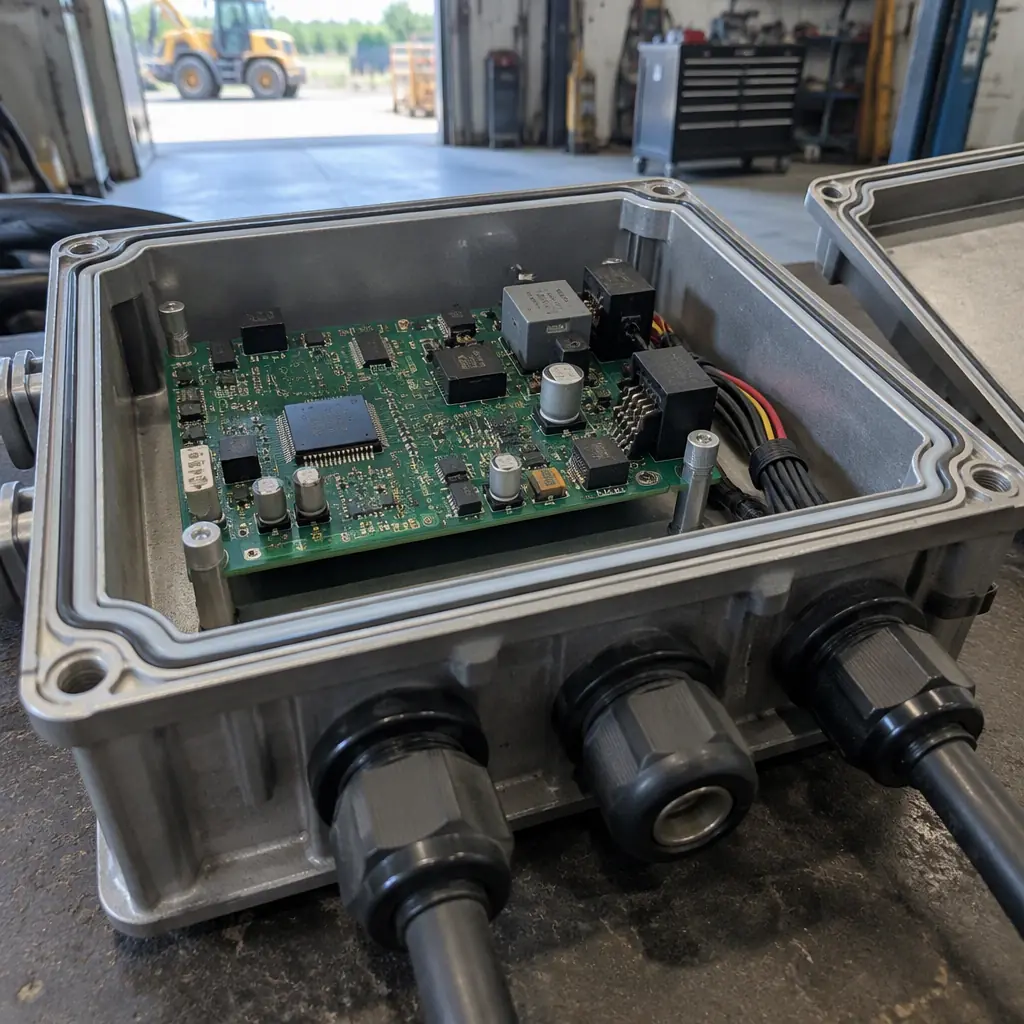
A farm machine's electrical system is hostile to electronics. ISO 7637-2 and ISO 16750-2 define the pulses the board must survive: load dump from an alternator can reach chassis-referenced peaks well above 100 V on a 24V system, inductive switching from hydraulic solenoids produces fast repetitive transients, and jump-starting from a second machine produces over-voltage and reverse-polarity events.
| Threat | Reference standard | Board-level mitigation |
|---|---|---|
| Load dump | ISO 16750-2 | Transient suppressor sized to clamp above 40 V, plus series input resistance |
| Reverse polarity | ISO 16750-2 | Series P-channel MOSFET or ideal-diode controller, not a shunt diode |
| Inductive switching | ISO 7637-2 pulse 1/2a | Input TVS plus bulk capacitance within 10 mm of the connector |
| Fast transients and ESD | IEC 61000-4-2 / -4-4 | ESD array on every external signal line before the connector |
| Ground offsets between chassis and sensor | Field practice | Isolated sensor interfaces or differential inputs with common-mode range |
For a 24V system, the load-dump clamp needs to tolerate the alternator's regulated output plus margin while still protecting downstream regulators, and the TVS must be placed so that its clamping path does not run the transient current through the signal ground. Reverse-polarity protection deserves particular attention: a series shunt diode that dissipates the full operating current will run hot and steal voltage headroom, which is why an ideal-diode or MOSFET configuration is the better choice on any board drawing more than an amp.
Temperature, Vibration And Dust
The three remaining stressors interact. A board that runs hot softens the conformal coating and the solder mask adhesion; vibration then fatigues the large components; dust ingress abrades the seal that was keeping moisture out.
Design for −40°C to +85°C ambient
Specify components rated to at least the full ambient range, not to the commercial 0–70°C band, and account for self-heating in the derating. Electrolytic capacitors are usually the first part to fail on cold start, so specify a low-temperature series or replace them with polymer types where the position allows. Our PCB materials guide covers the laminate side of the same problem.
Secure every heavy part, or vibration will do it for you
Relays, transformers, connectors, and large electrolytics are the parts that crack solder joints under continuous vibration. Use through-hole or press-fit where the mass justifies it, add corner-bonding or staking adhesive to large SMD parts, and confirm the staking does not mechanically load the joint in the wrong direction. The generic principles are in our vibration and shock testing guide.
Design the connector interface before the board
Most field failures are at the connector, not on the board. Choose sealed, keyed harness connectors, add strain relief so the cable load never reaches the solder joint, and prefer a connector whose mating cycle rating matches how often a technician will actually unplug it. Plating choice matters too: hard gold on mating surfaces survives far more cycles than a thin immersion finish.

What Evidence To Require From An Assembly Partner
Ruggedisation claims without test evidence are marketing. When you qualify an assembly supplier for agricultural electronics, ask for these specific artefacts and reject vague answers.
| Claim | Evidence to request | Where it is easy to bluff |
|---|---|---|
| "We apply conformal coating" | Coating thickness measurement per IPC-A-610 section 10, with a batch report | Thickness is often asserted, never measured |
| "Our boards are clean" | Ionic contamination test results with method and limit stated | No stated limit means no test |
| "Ruggedised for vibration" | Staking and corner-bond photographs plus the procedure used | Staking is claimed but not applied to the heavy parts |
| "Survives load dump" | Board-level transient test report naming the pulse and the clamp voltage | Component datasheet is quoted instead of a board test |
| "Consistent process" | SPC data on the coating and print processes, with Cpk | Single-sample results presented as capability |
The PPAP guide explains the packaging of this evidence for a production part, and our PPAP guide for conformal coated assemblies covers the coating-specific records. If your program is in the design phase and unusually sensitive to field failure, a manufacturing FMEA on the coating, sealing and connector steps is the highest-value document you can ask for.
Summary: Ruggedise In This Order
Seal the enclosure and specify an IP rating with a real gasket groove. Coat the board as a second line of defence, choosing the chemistry from the chemical exposure and verifying the thickness. Clean to a stated ionic limit before coating. Protect the input against load dump, reverse polarity and inductive switching, with the TVS placed so the clamp current does not cross signal ground. Design for the full −40°C to +85°C ambient with components rated for it, stake every heavy part, and treat the connector as the reliability-critical component it is. Then require test evidence for each claim.
At Huaxing PCBA we build 8 SMT lines running conformal coating, staking and ionic contamination testing in-house, with IPC-A-610 coating verification and batch-level thickness reporting on coated agricultural and industrial assemblies. We offer 24-hour quick-turn builds for field trials and a free DFM review that covers sealing, coating and connector selection for your enclosure. Send your Gerber and BOM for a quote or talk to an engineer about your field environment.
