
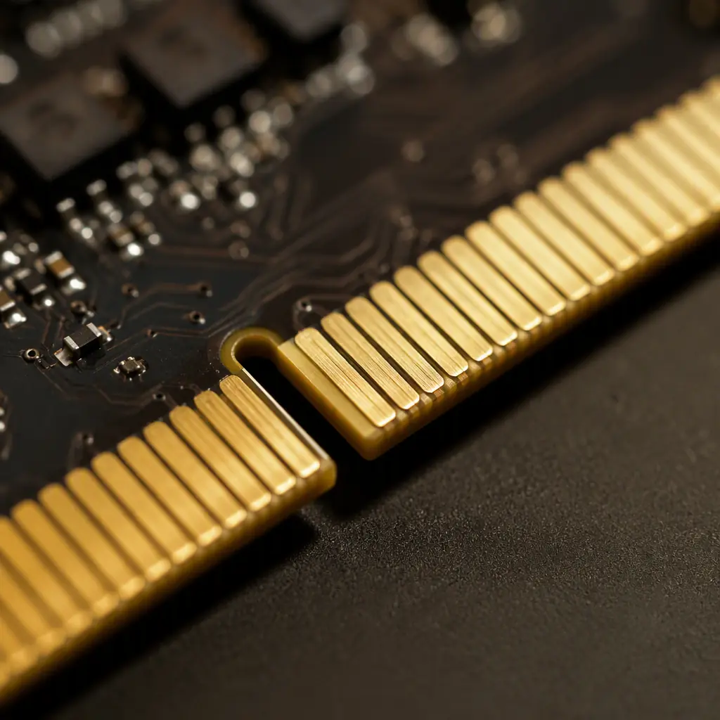
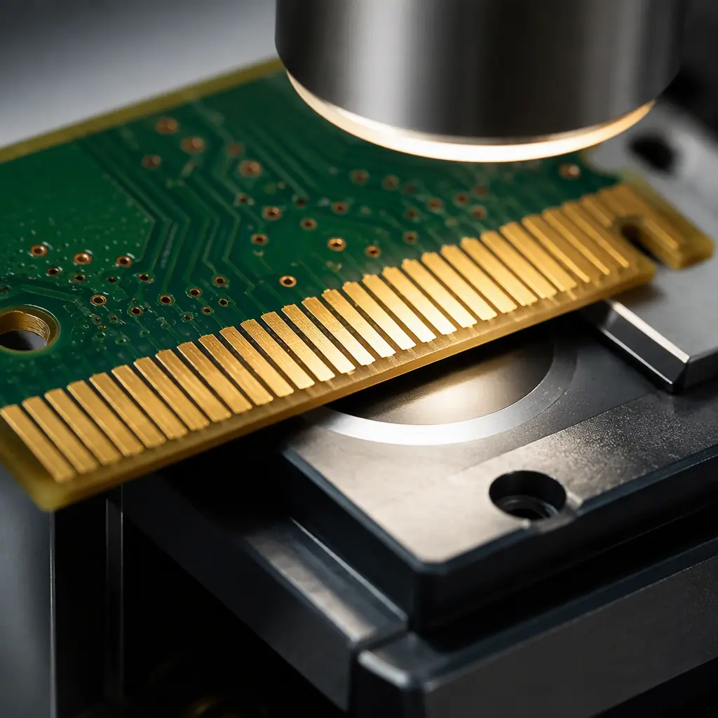
A memory DIMM, a graphics card, a blade server, a proprietary edge connector on a daughtercard, all of them share the same weak point: the row of gold-plated contact pads on the board edge that mate with a socket. It looks simple, but it is a controlled-wear, controlled-corrosion system, and it is specified differently from every other surface finish on the board.
At Huaxing PCBA we fabricate boards up to 32 layers with 6 oz copper and a full range of finishes, and we plate card-edge gold to spec, with selective plating. So the gold fingers can be hard gold while the rest of the board stays on a cheaper finish. That combination is where most of the saving, and most of the risk, lives.
Why The Edge Connector Is Different From Every Other Finish
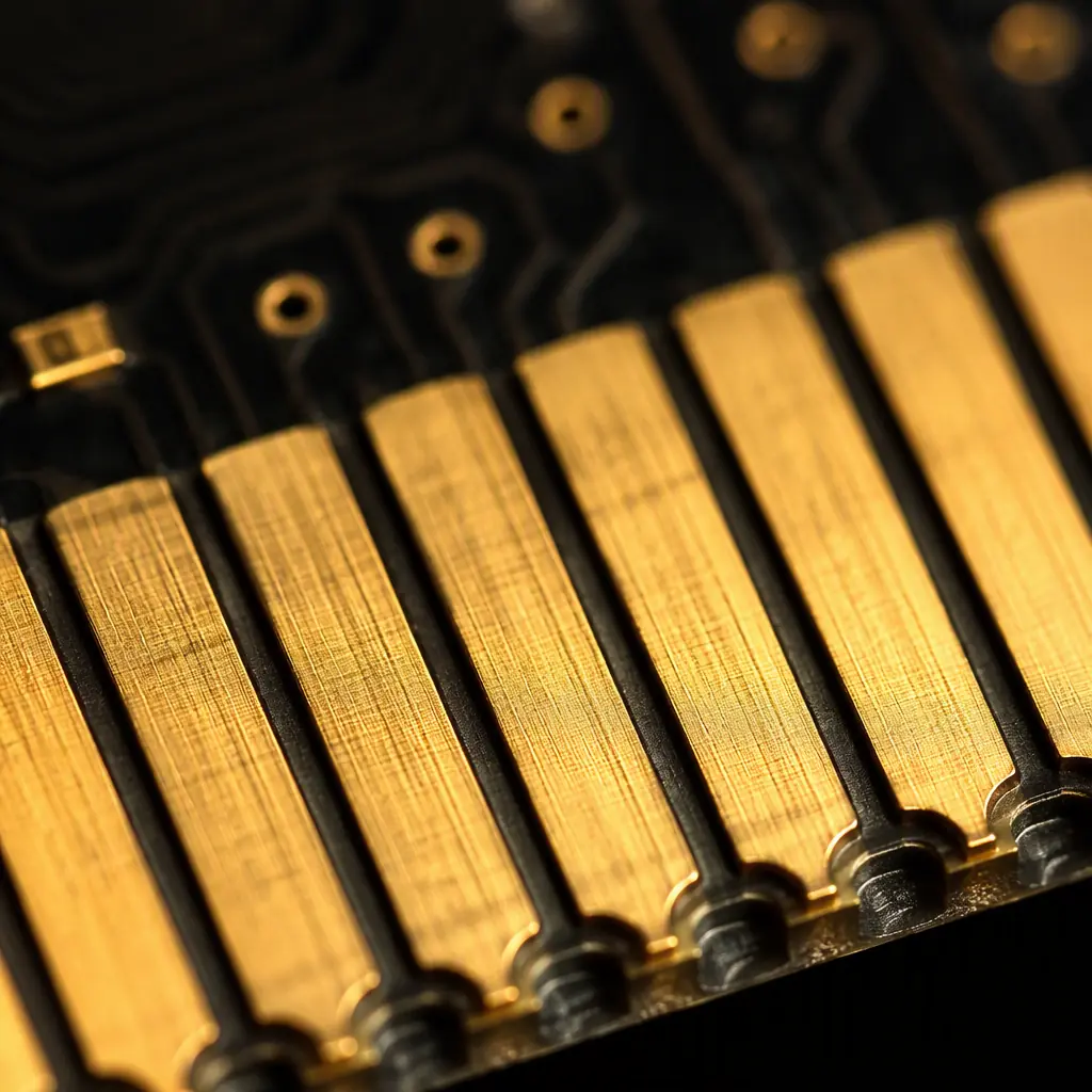
The rest of the board is a static environment: it gets soldered once and then sits there. The card edge is different. It is rubbed by a socket every time the board is inserted, exposed to whatever the socket wipes onto it, and it has to keep its electrical contact through thousands of mating cycles, humidity, and the occasional hot-swap that was never in the datasheet. That is why the spec is not "gold-plated". It is a package of thickness, hardness, nickel barrier, bevel and cleaning.
Hard Gold Vs Soft Gold: It Is Not The Same Process
This is the single most misunderstood point, and it is where boards go wrong. There are two kinds of gold plating, and they are suited to entirely different jobs:
| Property | Soft gold (ENIG / ENEPIG) | Hard gold (electrolytic) |
|---|---|---|
| Hardness | Soft, lower wear resistance | Tough, high wear resistance |
| Thickness | Typically 0.05–0.1 µm | Typically 0.5–2.0 µm |
| Best for | Wire bonding, solder pads | Card edge, sliders, switch contacts |
| Cost | Lower | Higher (electrolytic + selective) |
For an edge connector that gets inserted repeatedly, you want hard gold. Soft gold from an electroless nickel-immersion gold line (the finish used on most ENIG boards) will wear through in a fraction of the cycles. Our hard gold vs soft gold guide goes deeper into the metallurgy.
Note: Because hard gold is an electrolytic process, it usually has to be applied selectively, you cannot plate the whole board in hard gold. That is why you see a long, gold row of fingers on the edge and a cheaper finish everywhere else. This is a selective plating job, and it is exactly the kind of thing that has to be designed in, not assumed.
Gold Thickness: The Number That Predicts Life
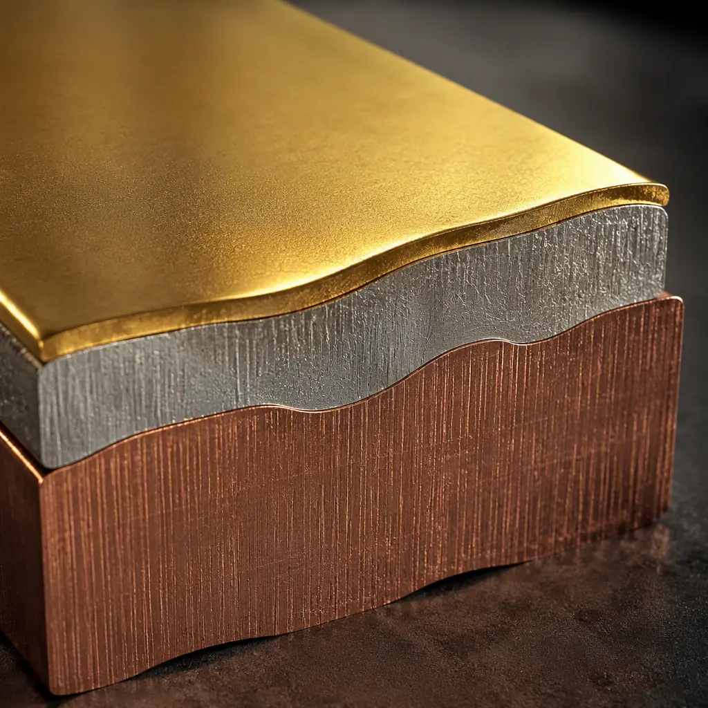
Gold is a wear surface, so thickness is the dominant life driver. Too thin and the gold disappears after a modest number of insertions, exposing the nickel underneath and oxidising the contact. The convention breaks down roughly as:
Under 1 µm, short-life / prototype
Fine for test and bring-up, not for a product with a real insertion-count requirement. This is a common cost-saving that shows up only after the unit is in the field.
1–2 µm, standard production edge connector
The typical spec for a card edge that will be cycled regularly. This is the sweet spot for most commercial hardware.
2–3 µm (and up), high-cycle industrial / server
Where the board is hot-swapped or lives in a server and the connector is serviced repeatedly. You pay for it, but you get the cycle life. Our surface finish selection guide shows the full trade-off.
The Nickel Barrier: The Unsung Layer
The gold you see is only the top layer. Under it sits a nickel barrier, usually 3 to 6 µm. Nickel does two jobs: it stops copper from diffusing up through the gold into the contact, and it provides the mechanical hardness that actually carries the load. If the nickel is skimped, the gold on top looks fine on day one but the contact degrades rapidly. Any spec that only mentions "gold" and not the nickel layer is incomplete.
Bevel And Chamfer: Easily Overlooked, Often Decisive
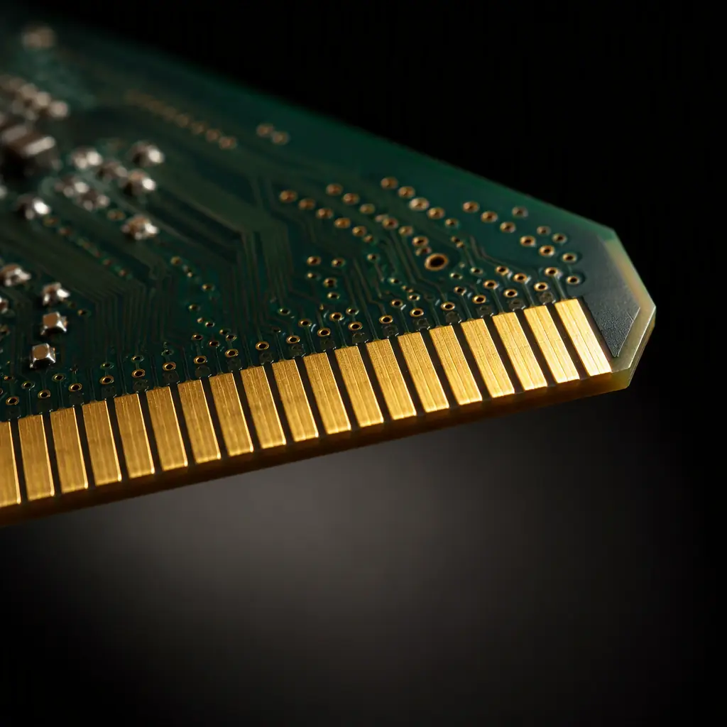
A card edge that has to slide into a socket is cut with a bevel. An angled chamfer on the edge of the board so the fingers do not catch on the socket ramp. If the bevel angle is wrong, too shallow, or absent, the board can bind or, worse, lift the socket contact. It is a small piece of geometry that decides whether the board seats cleanly. It should be left on, and its angle specified. This is the kind of detail that separates a factory that understands edge connectors from one that treats them as an afterthought.
Wear And Corrosion: What Actually Fails In The Field
The failures you will see from a poorly specified edge connector come in two flavours:
Wear-through from too-soft or too-thin gold
The gold wears off, exposing nickel, which oxidises and raises contact resistance. Intermittently, the board works, then stops, then works again. The classic intermittent-contact symptom that is a nightmare to diagnose remotely.
Corrosion from contamination or humidity
Residue on the fingers, or a board that was handled without the right cleanliness, can accelerate corrosion in high-humidity environments. This is where cleanliness and handling matter, and it is why a contamination control regime matters on a product with an exposed contact.
What To Put On Your Fabrication Drawing
To get an edge connector that survives, specify it precisely. Put the following in the fab drawing and the order:
Explicitly call out "hard gold / electrolytic gold" for the fingers
Do not rely on the general surface finish note to apply to the whole board. A card edge is the one place you want hard gold selectively applied. See our selective plating guide for the technique.
State gold and nickel thickness with tolerance
e.g. "1.5–2.0 µm hard gold over 3–6 µm nickel". No tolerance on a wear surface is not a spec.
Define the bevel angle and depth
Be explicit about the bevel so the board seats into the socket cleanly and the fingers are not scraped on insertion.
Require the plating thickness verification
Gold thickness is verified with X-ray fluorescence (XRF), not by eye. Ask for the measurement. Cross-reference against our cross-section report guidance so you can read the evidence.
The 10-Second Buyer's Checklist
Key Takeaway: A card-edge connector is a wear-and-corrosion system, not a cosmetic surface finish. Specify hard gold selectively applied at a real thickness (typically 1–2 µm) over an adequate nickel barrier, define the bevel so the board seats cleanly, and verify gold thickness with XRF rather than a glance. Get those four things right and the connector will outlast the rest of the board; get them wrong and you have an intermittent fault you cannot reproduce.
Summary. The Edge Is A Wear Surface, So Spec It Like One
The edge connector is the last thing most teams think about and the first thing that shows wear in a product with a real service life. It does not need to be exotic. It needs to be specified correctly: hard gold, real thickness, a nickel barrier, a proper bevel, and verified. That is a short list, and every item on it is checkable.
At Huaxing PCBA we plate card-edge gold to spec, in hard gold with a controlled nickel barrier and a correctly cut bevel, and we verify plating thickness with XRF on every run. We fabricate up to 32 layers and 6 oz copper, are ISO 9001, IATF 16949 and UL certified, and can redesign the finish stack on an existing board to get you the cycle life you need without paying for gold you do not need. Upload your files for a quote or talk to a project manager about your edge-connector requirements.
