
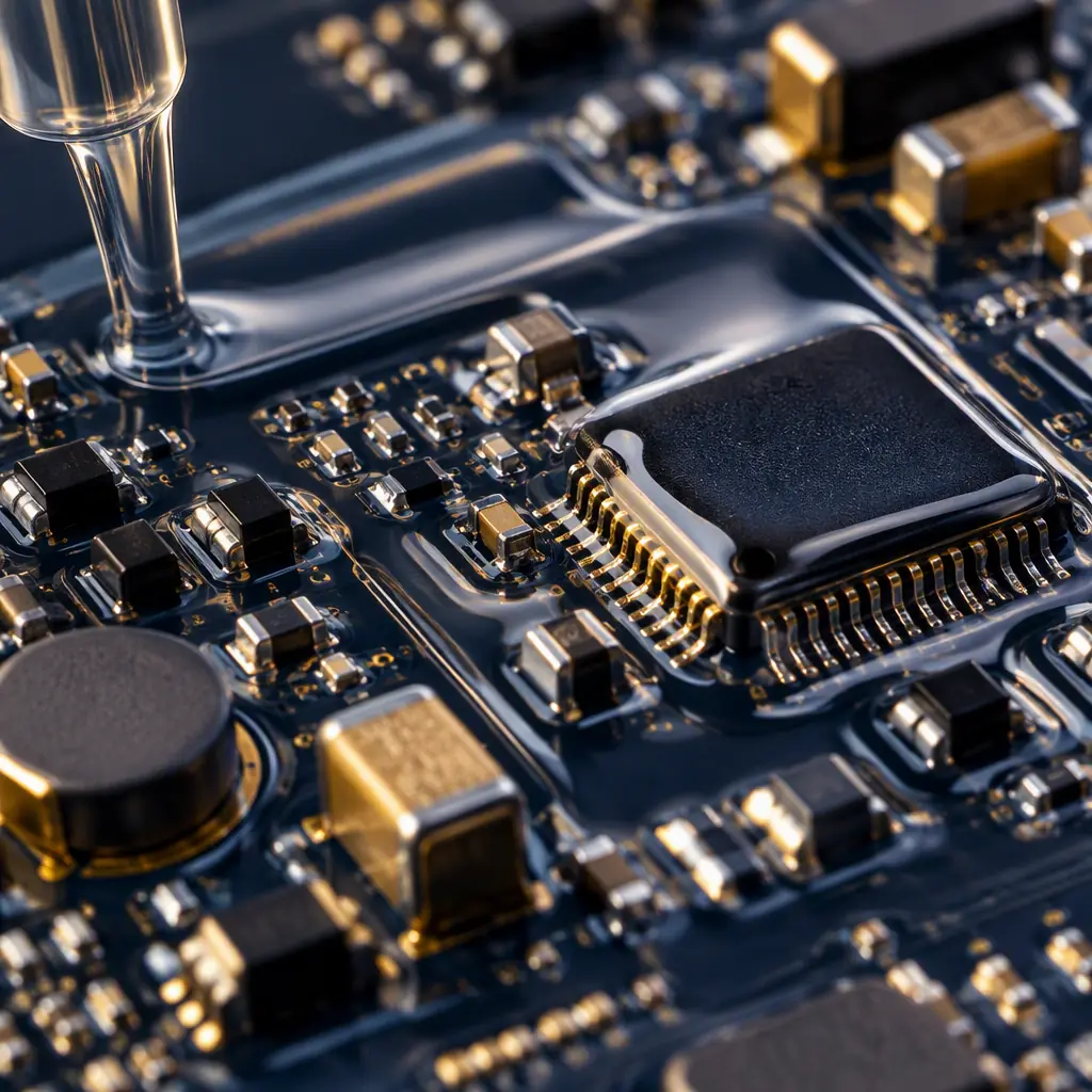
Conformal coating is applied to protect a finished assembly from moisture, ionic contamination and electrochemical migration, and the protection it provides is a direct function of film thickness on the surfaces that matter. Too thin and the coating does not form a continuous barrier over the sharp edges, component tops and lead shoulders where moisture actually collects. Too thick and you introduce cure stress, cracking over thermal cycling, and masking problems on connectors that must stay solderable. The difficulty is that thickness is genuinely hard to measure on a populated board, and the widely used methods each report a different number for the same coating.
This guide covers what IPC-CC-830 actually requires, how the four practical measurement methods differ, and how to build a thickness control that holds across a production run rather than only on the qualification coupon.
What IPC-CC-830 Requires
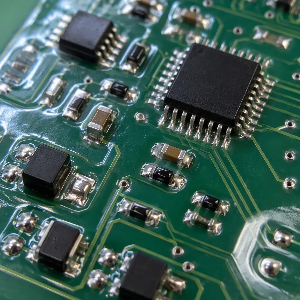
IPC-CC-830 is the qualification and performance specification for insulating compound used as conformal coating. It does not set a single universal thickness for all products. Instead it sets qualification requirements for the material - dielectric withstand, moisture resistance, thermal shock, fungus resistance - and then the applied thickness is set by the product's performance class and the coating type, agreed between the user and the coater.
In practice most commercial and industrial assemblies land in a working range of 25 to 75 µm for acrylic and urethane systems and 12 to 50 µm for parylene, with the exact figure driven by the standard the product must meet. Where a customer invokes IPC-A-610 for acceptance, the coating sections are inspection criteria rather than thickness mandates, and where a military or aerospace standard applies, minimum thickness is usually stated explicitly per coating type.
| Coating type | Typical applied thickness | Thickness measurement difficulty |
|---|---|---|
| Acrylic (AR) | 25 - 75 µm | Low - easy to build up in layers, tolerant of variation |
| Polyurethane (UR) | 25 - 75 µm | Moderate - solvent-based, thickness varies with spray pattern |
| Silicone (SR) | 50 - 200 µm | Moderate - thick films, but soft and easily compressed by gauges |
| Parylene (XY) | 12 - 50 µm | High - vacuum deposited, extremely uniform but very thin to measure |
| UV-cure acrylic | 75 - 250 µm | Moderate - shadow areas cure differently from exposed areas |
The table is a starting point, not a specification. The number that governs a given programme comes from the standard invoked in the contract and from the field environment the board will see.
The Four Measurement Methods and Why They Disagree
Every method for measuring coating thickness on a populated board has a different physical basis, and each one answers a slightly different question. Knowing which question you are asking prevents most acceptance arguments.
Wet-Film Gauge
Measured immediately after application, before cure, on a flat test coupon or an unpopulated area of the panel. This is the most useful production control because it catches a drifting spray pattern or a clogging nozzle within minutes rather than at final inspection. The limitation is that wet-film thickness is not what the product actually gets: solvent loss during cure removes a significant fraction of the film depending on the coating type, so a wet-film reading must be correlated to a cured-film result before it can be used as a limit. Establish the wet-to-cured ratio for the specific material and process, then control the wet film.
Ultrasonic or Magnetic Gauge on a Coupon
A coupon coated in the same pass as the production boards gives a cured-film reading that is quick and non-destructive. The coupon must travel through the process attached to the production panel or processed in the identical rack position, because spray coverage is positional. A coupon coated separately will read differently. This method is the practical workhorse for spray processes and is normally the acceptance measurement, with the caveat that it measures a flat coupon rather than the component shoulders and edges where the product is most at risk.
Microsection on a Witness Board
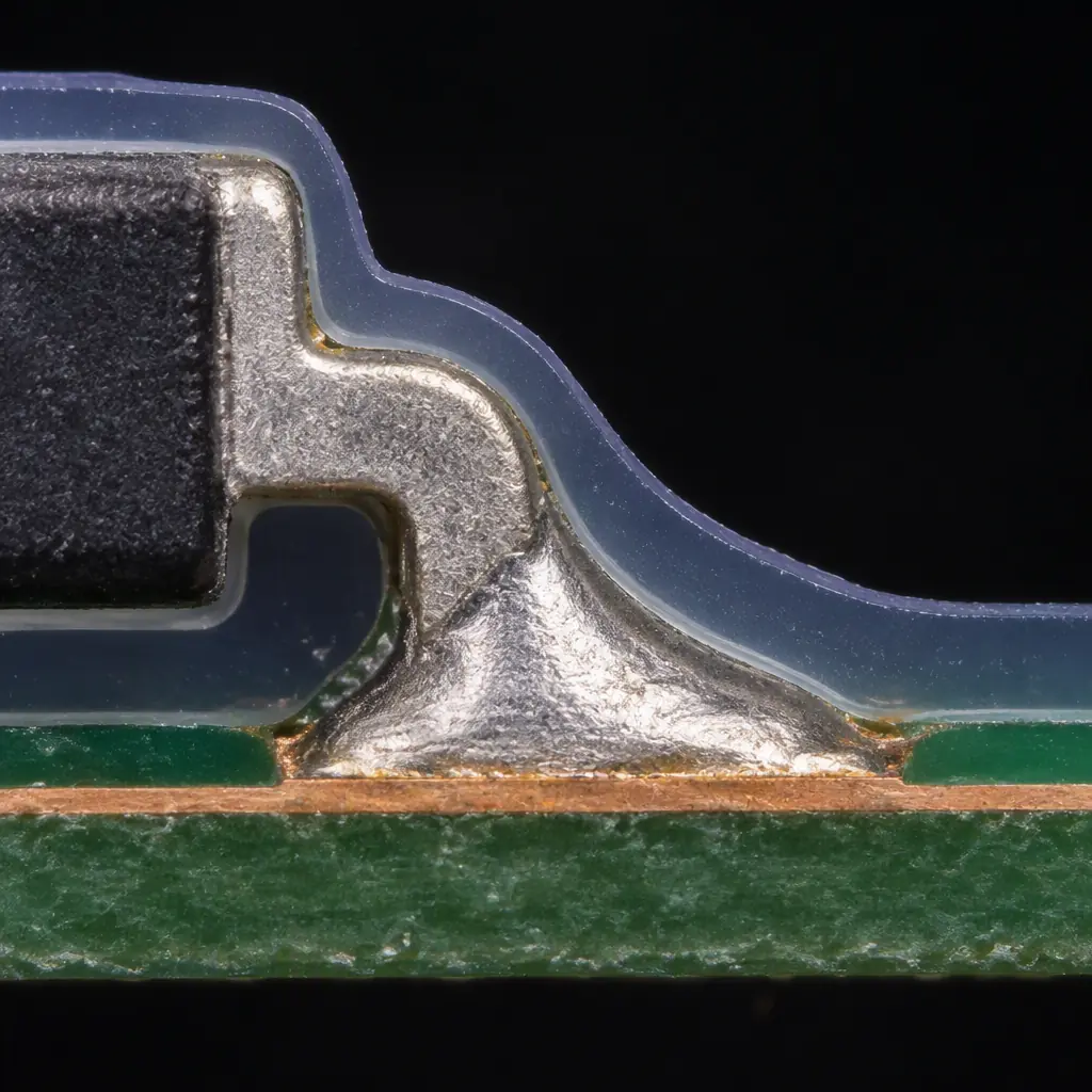
The only method that shows actual thickness on actual geometry - over a lead shoulder, down a component side wall, across an edge where the coating thins. It is destructive, so it is performed on a witness board processed with the batch or on a sacrificial production board. Microsection is the reference method when a programme is being qualified, and it is the method that reveals the difference between nominal coupon thickness and the thin spots that actually govern protection. Require at least one microsection at qualification and periodic sections thereafter.
Non-Contact Optical or Terahertz
Optical methods measure a cured film without contact and can be scanned across a board, which makes them attractive for 100% inspection. Their accuracy depends on the coating being optically uniform and on the substrate reflectance being known, so heavily shadowed areas, transparent coatings over mirrored surfaces and thick silicone films are all harder to measure reliably. Where available, these systems are most useful as a screen for gross coating misses rather than as a certificate of thickness.
Why methods disagree: a wet-film gauge reading does not equal a cured-film reading; a coupon reading does not equal a reading over a component shoulder; and an optical scan over a matte surface does not equal a microsection. When two parties disagree about thickness, the first question to ask is not which number is right, but which surface each number describes.
Building a Thickness Control That Holds
Thickness variation on a spray line comes from a small number of dominant sources, and controlling them is cheaper than inspecting the output harder.
| Source of variation | Observed effect | Control |
|---|---|---|
| Viscosity drift of the coating bath | Film thins gradually across a shift as solvent evaporates | Log viscosity at intervals; top up per material datasheet rather than by feel |
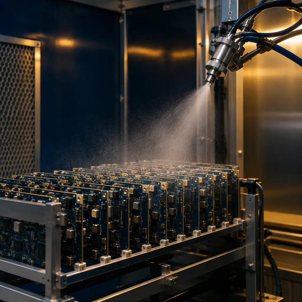
| Spray pattern and nozzle clogging | Localised thin patches and missed component tops | Wet-film coupon at the start of each batch and after any nozzle change |
| Board orientation and rack position | Edges and shadowed sides read thin relative to the centre | Rotate boards through the process or coat two passes at 90 degrees |
| Component height and density | Tall parts shadow neighbours; high density holds more coating | Adjust passes by assembly class, not one recipe for all boards |
| Cure schedule | Under-cure leaves a soft film that reads thick and performs poorly | Verify cure by solvent rub or DSC, not by time-in-oven alone |
Two passes at reduced thickness with a ninety-degree rotation is the standard answer to edge and shadow coverage, and it also improves thickness uniformity more than any amount of gauge calibration. A second pass does not double the thickness on flat areas in the way a naive calculation predicts, because the second pass fills and levels the first, but it reliably lifts the thin regions.
Thickness, Masking and the Interface Problem
Thickness does not exist in isolation. Every region that must remain solderable, conductive or mateable has to be masked, and the masking method constrains how thick the coating can be without wicking into prohibited areas. If a connector has a 0.5 mm gap between contacts and the coating is applied at 200 µm, capillary action will pull coating into the mating interface regardless of how well the mask is placed.
The practical rule is to settle thickness and masking together, before the first production board, and to verify the pairing on a real assembly rather than a test coupon. Masking selection is covered in detail in our conformal coating masking guide, which covers tape, boots, peelable mask and dispense-free options. Where coating has to be removed for rework, the chemistry-specific approach is covered in conformal coating removal and rework.
Inspection and Acceptance Criteria
Coating acceptance under IPC-A-610 is judged on coverage and defects rather than a single thickness number: the coating must be continuous over the required areas, free of voids, bubbles, cracks, orange-peel and delamination, and must not bridge between conductive features that are meant to remain isolated. Thickness records support the acceptance decision, they do not replace inspection.
A workable acceptance package combines a cured-film coupon reading per batch with a defined limit range, a wet-film reading at the start of each batch as a process control, a microsection at qualification and at a defined periodic interval, and a visual inspection against the IPC-A-610 coating criteria with the inspection area recorded. Retain the coupons with the batch records so a thickness claim can be traced to a physical artefact rather than a log entry.
Frequently Asked Questions
What is the minimum conformal coating thickness for IPC-CC-830?
IPC-CC-830 qualifies the material rather than mandating one thickness. The applied minimum is set by the product standard and coating type, commonly 25 µm for acrylic and urethane and 12 µm for parylene. Where a military or aerospace standard applies, it usually states a minimum explicitly, so quote that standard rather than IPC-CC-830 alone when specifying.
Can I verify thickness without destroying a board?
Yes, using an ultrasonic or magnetic gauge on a coupon that travelled through the process with the production boards. That gives a cured-film reading per batch. It measures a flat coupon, so pair it with periodic microsections to confirm the coating is also adequate over component shoulders and edges.
Why does my wet-film reading differ from the final thickness?
Because solvent evaporates during cure. The wet-to-cured relationship depends on the material solids content and the cure schedule. Establish the ratio for your specific material once, then use wet-film readings as a fast process control expressed in cured-film equivalents.
Does a thicker coating always protect better?
No. Beyond a point, additional thickness adds cure stress, increases the risk of cracking over thermal cycling, and makes masking and rework harder without improving the barrier. The useful improvement is uniformity at the thin points, not average thickness.
