
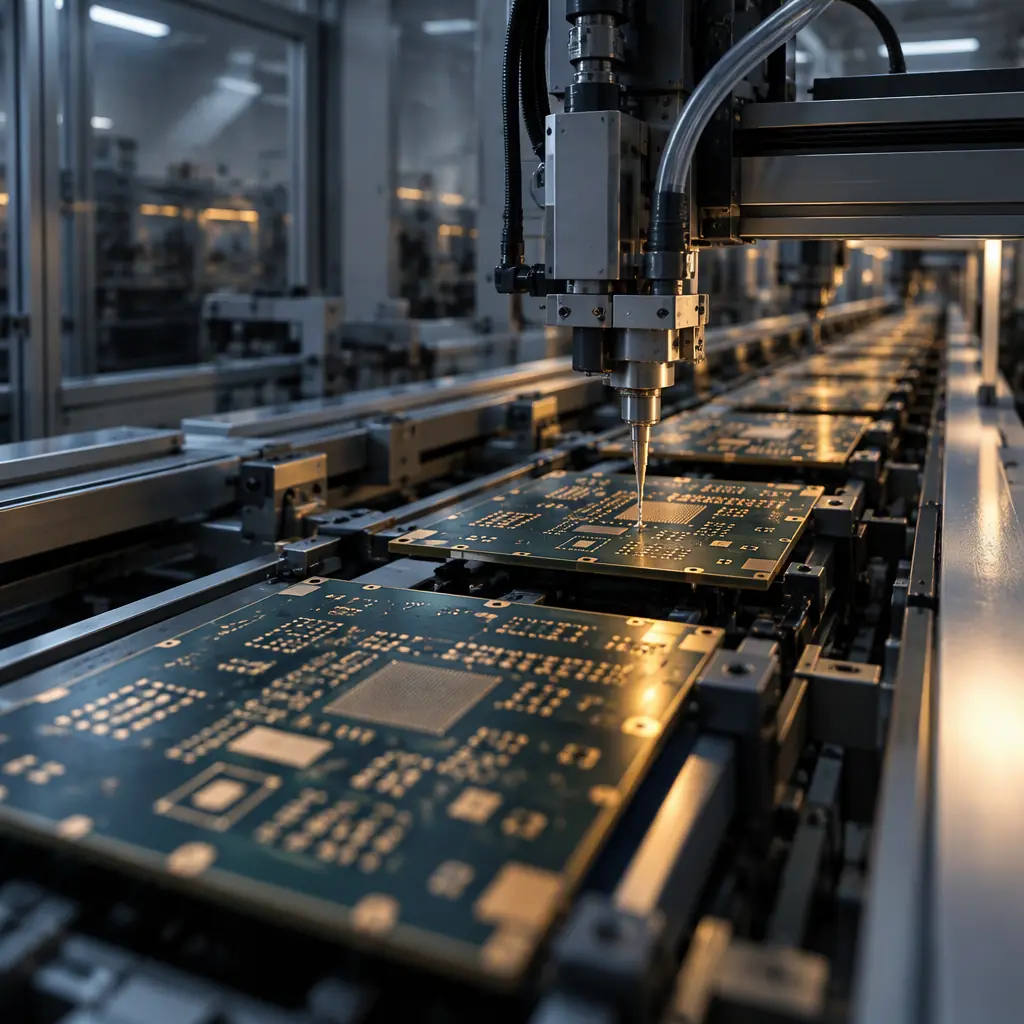
Most of the writing about stencil-free assembly stops at the cost model. That is the right place to start — a jetting dispenser only makes sense below a certain lot size, and that comparison is covered in solder paste jetting versus stencil printing. But once a buyer has decided to evaluate jetting for a real program, the next question is not financial. It is structural: what does the line look like when the printer is gone? A stencil printer is not merely a machine that applies solder paste — it is the mechanical anchor of the front of an SMT line, and removing it moves four things at once.
What a Stencil Printer Does That a Jetter Does Not
A stencil printer applies paste through a metal foil in one squeegee stroke. The whole panel receives paste at once, and the volume deposited is governed by the aperture geometry — specifically the area ratio, the ratio of aperture opening area to aperture wall area. The industry rule of thumb is that an area ratio below 0.66 gives unreliable paste release, which is why fine-pitch apertures are the first thing a printing engineer argues about. The printer also fixes the panel hard against a tooling plate and presses the stencil down onto it, so the board is mechanically constrained while paste is deposited.
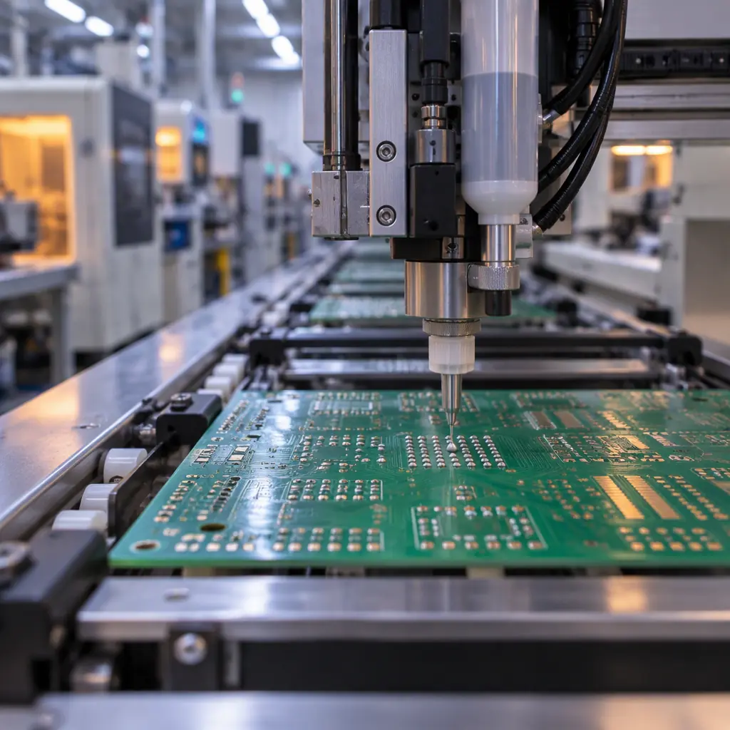
A jetting dispenser does the opposite. It deposits paste as discrete dots, typically in the 5–20 nL range per dot, placed by an X-Y gantry under vision guidance. There is no stencil, so there is no aperture to release paste from and no area-ratio constraint — the practical fine-pitch limit is set by dot placement accuracy, not foil geometry. That is the real engineering advantage of a stencil-free line, and it is why the technology earns its place on dense mixed-technology boards. The trade is time: a stencil print cycle runs 15–25 seconds per panel, while a jetting pass over an equivalent panel commonly runs 40–90 seconds depending on dot count and dispenser speed. That single fact reshapes the line.
Machine Position and Line Sequence Changes
On a conventional line the printer sits at the head of the line: bare panel in, paste printed, into SPI, into the placement machines, into reflow. The jetter is not forced into that position. It can run inline in the same slot, run inline mid-line, or sit offline as a batch operation feeding a loader. Each choice changes how the line is balanced, and the wrong one is how a jetting line ends up slower than the printer it replaced even though the paste process itself is fine.
| Layout | How It Runs | Best For | Watch Out For |
|---|---|---|---|
| Jetter inline, front of line | Replaces the printer in the same slot | Programs where every board is jetted | Jetter cycle becomes line takt; downstream machines starve if it is slow |
| Jetter inline, mid-line | Paste applied after some placements or after a first reflow | Adding paste for a second-pass or mixed-technology step | Conveyor reversal and board tracking must be handled explicitly |
| Jetter offline / batch | Panels jetted in batches, then loaded to the SMT line | Prototype and NPI work alongside a running stencil line | Paste dwell time before reflow; double handling; WIP buffer space |
For most high-mix programs the honest answer is that the jetter starts offline. It runs the prototype and low-volume lots in batches while the stencil line keeps producing the high-volume work, which is exactly the transition path described in stencil-free SMT for NPI and prototypes. Only when a program's volume is stable and low enough that no stencil is ever tooled does an inline front-of-line position make sense — and even then the line has to be re-balanced, because the jetter cycle is now the line's takt rather than the printer's.
Board Support, Clamping and Vision Alignment Without a Stencil
A stencil printer mechanically solves several problems that a jetter does not. When the stencil is pressed onto the panel, the panel is held flat and the paste is forced into the apertures against a tooling surface. Remove the stencil and the panel must hold itself flat and still while the dispenser gantry travels over it — at speed, with a camera actively locating fiducials. Board support stops being an afterthought and becomes a design constraint on the tooling.
Support the panel where it will actually bow
Panels warp between reflow cycles. A jetter has no printing pressure to flatten the board, so support pins, vacuum chucks or a machined tooling plate must reach the areas that sag — usually the panel centre and the thinnest strip between breakaway rails.
Confirm fiducial contrast for the dispenser camera
The jetter aligns to fiducials with its own camera, not to the stencil frame. Fiducial size, contrast and placement all matter more here, and the rules are the same ones that govern fiducial mark design. A fiducial that a printer could find through a stencil aperture may not be reliable for direct camera capture.
Design the tooling for one panel, not one product
Because there is no stencil to change, the changeover saving on a jetting line comes from the tooling. Tools that accept a family of panels keep the changeover to a software load; bespoke per-panel tools give the changeover right back.
Plan for the panel not being pressed flat
Dot placement accuracy is quoted in the ideal case. On a warped panel the dispenser's Z axis has to follow the surface, and any height variation beyond the dispenser's working range turns into dot volume variation — the same defect class you would otherwise chase with an SPI.
Keep the SPI, change what it is checking
Inspection of paste volume still matters, but on a jetting line the failure modes shift from stencil-related defects (smeared paste, bridging from over-print) to dot-count and placement errors. The measurement thresholds need to be re-derived rather than copied from the stencil program.
Paste Handling: Tank, Cartridge and Nozzle Cleanliness
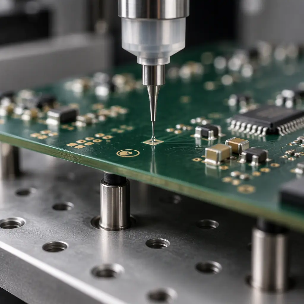
This is the change that catches out teams who assumed a jetter was just a printer replacement. A stencil printer opens a jar of paste, spreads it, and the operator scrapes the excess back. A jetter pushes paste through a small orifice from a cartridge or syringe under pressure, and that changes the entire paste-management discipline.
The paste is now in a sealed container with a pot life that starts the moment the cartridge is opened — commonly 8–12 hours for a standard no-clean jetting paste at typical shop-floor temperature, and the container cannot simply be re-covered. Nozzle capping and purge behaviour matters: an uncapped nozzle during even a short pause can skin over, and the first dots after a resume may be low-volume. In practice a jetting line consumes a small but real quantity of paste to purge and waste per shift — often grams per day on a lightly loaded line — which is invisible on a stencil line that barely wastes anything.
The practical consequence is that a stencil-free line needs a written paste-management procedure where a stencil line only needs a paste log. Specify cartridge size against the daily consumption so the paste is used within pot life, define the pause threshold at which a nozzle is capped or automatically purged, define the purge count after a resume, and record cartridge open time on the traveller. The paste itself is selected differently too — the formulations that jet cleanly are not always the ones that print cleanly, which is why dispenser and paste selection is a joint decision rather than two separate ones.
Line Balancing and Takt: Is a Stencil-Free Line Faster?
Short answer: usually not per board, but often per lot. A jetting pass places dots serially — the gantry visits each deposit location in turn — whereas a stencil transfers the whole pattern in a single squeegee stroke. On a board with a few thousand paste deposits, jetting commonly takes two to four times the print cycle of the same panel. On its own, that makes the jetter the slowest machine on the line, and if it sits at the front of the line it sets the takt for everything downstream.
The saving is in the changeover. A stencil changeover is a physical event: print the previous stencil off the machine, change the tooling, load and tension the new stencil, run the first-article print, and re-verify paste volume. Allow 30–90 minutes of lost line time depending on how much tooling is involved. A jetting changeover is a program load plus, if the tooling is family-based, nothing else. When the number of lots per week is high and the lots are small, the cumulative changeover saving overtakes the per-board cycle penalty below roughly 500 boards per lot. That is the crossover that should decide the layout: if the program sits well below it, the offline or inline-at-low-volume layout wins; if it sits above it, the stencil line is still the right tool.
For the wider picture on how a line's takt is calculated and where the real bottleneck sits, the method is the same as any line planning exercise and is covered in SMT line capacity and throughput planning.
Staffing and the Skill Shift
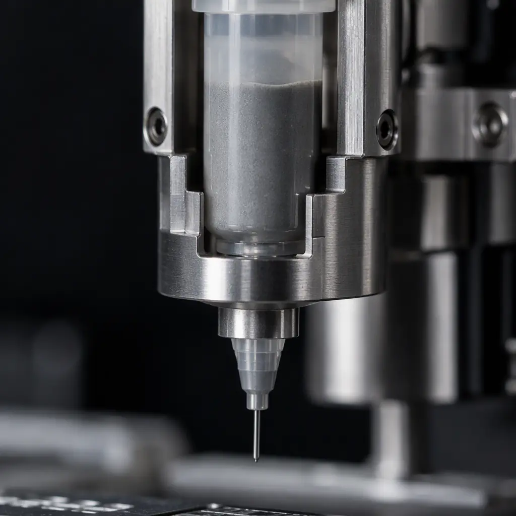
A stencil line is operated by people who understand tooling, tension and print pressure — mechanical, visible problems. A jetting line is operated by people who understand dispenser parameters, nozzle condition and software offsets, and whose failures are invisible until inspection. That is a genuine retraining task, not a same-person-different-machine swap.
Three roles shift. The printer operator becomes a dispenser technician whose routine is parameter and nozzle management rather than tooling. Maintenance changes from stencil handling and machine mechanicals to dispenser fluidics — nozzle replacement, cartridge seals, pressure regulation. And a new spare-parts inventory appears: nozzles, cartridges and seals, all of which are consumables with finite life and lead times that must be planned before the line goes live, not after the first unplanned stop. Programs that treat this as an unplanned detail find the savings from the jetting line eaten by downtime in the first quarter. Teams that plan the changeover properly find it behaves exactly as the process qualification predicted.
At Huaxing PCBA we run both conventions in Shenzhen — 8 SMT lines with stencil printing for volume programs and jetting capability for high-mix and NPI work — so the paste process is chosen on lot economics rather than on what a single line can do. Boards are built to IPC-A-610 Class 2 and 3 across the full line. Send your Gerber and BOM and we will tell you which convention your program actually suits, or talk to a process engineer about re-laying out a line around jetting.
