
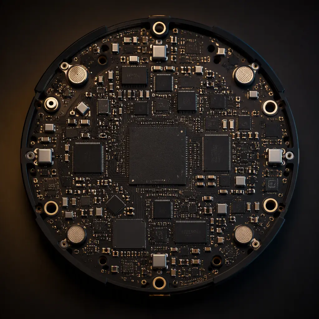
A smart speaker is a contradiction on one board: it must hear a whisper from 3–5 meters away while its own Class-D amplifier pushes 10–30 W of audio, its Wi-Fi radio transmits a few centimeters from the microphones, and its power supply hums at line frequency. Every one of those aggressors couples into the audio path through the PCB unless the layout stops it. The products that win voice-assistant reviews are the ones whose boards keep the microphone array's signal-to-noise ratio above 60 dB under full-volume playback. That is a layout achievement, not a firmware one.
This guide covers the four disciplines that decide smart speaker voice performance: microphone array geometry and placement, clean power and grounding for the analog audio path, Class-D amplifier and speaker output layout, and Wi-Fi/Bluetooth coexistence. It closes with the manufacturing and test steps that verify voice quality at volume. Huaxing PCBA assembles consumer audio boards across 8 SMT lines: including TWS earbud boards . And the same rules that protect a 6-mic far-field array scale down to every audio product we build.
Microphone Array Design: Count, Spacing and Placement
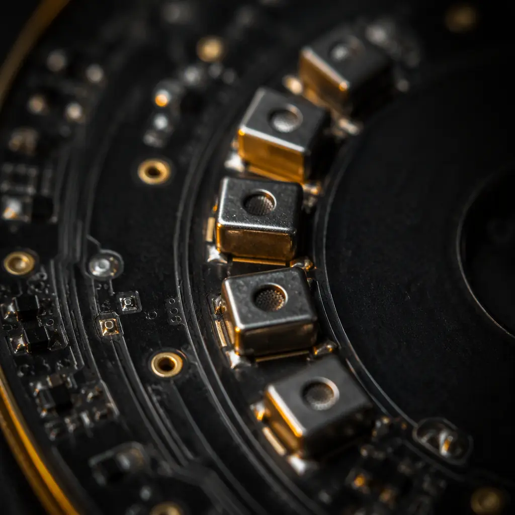
Far-field voice processing, beamforming, echo cancellation and wake-word detection, depends on the array's geometry. The DSP can only work with what the PCB gives it: microphone positions, apertures and orientation are fixed in copper.
Four to six mics, spaced 30–50 mm apart
A 2-mic array handles basic echo cancellation; 4–6 mics enable true beamforming with 360° coverage. The spacing window of 30–50 mm matches the wavelength range of human speech (roughly 15–70 cm at 500 Hz–4 kHz), which is what beamforming algorithms expect. Closer spacing blurs the time-of-arrival differences; wider spacing creates spatial aliasing.
Place mics on the perimeter, not the center
Mics should sit near the outer edge of the board, distributed around the circumference, with the acoustic ports facing the enclosure's microphone apertures. The distance between each mic and its port must be identical, a 2 mm difference changes the arrival time and degrades the beamformer. Keep the mic area free of tall components; the acoustic port needs a clear, unobstructed channel to the MEMS opening.
Route the PDM bus as a clean digital island
Most MEMS mics output PDM (pulse density modulation) on a shared data line clocked at 2.4–3.2 MHz, or I²S for higher-end codecs. The PDM clock is a digital aggressor, route it with a solid ground return, keep it away from the analog mic inputs, and add a series resistor at the source to slow the edges. Our MEMS sensor PCB guide covers the decoupling and grounding rules for the mic power pins.
Give every mic its own LDO or clean rail
MEMS mics have power supply rejection that falls off above a few kHz. A shared rail with the DSP's switching regulator injects ripple directly into the audio band. Use a dedicated low-noise LDO for the mic array, and place a 100 nF + 10 µF decoupling pair within 3 mm of each mic's VDD pin.
Key Takeaway: Mic placement is frozen at the layout stage. You cannot fix a 6-mic array that was routed to the wrong side of the board, sharing a noisy rail, with uneven port lengths, no amount of beamforming firmware will recover it. Treat the array as the most expensive component on the board.
Keeping the Audio Path Clean: Power and Grounding
The classic smart speaker failure mode is a 100 Hz (or 120 Hz) hum on the mic path, plus switching noise from the main regulator. Both are PCB problems before they are circuit problems.
Partition the ground plane: analog, digital and power
Use a single solid ground reference with strategic partitioning rather than split planes (splits create return-path discontinuities that radiate). The mic array, codec and DSP analog section sit in the quiet zone; the Class-D output stage and its filter, the Wi-Fi module, and the AC-DC input each get their own zone, connected to the main ground at one star point near the power input. Audio reference traces must never cross a zone boundary.
Keep the codec and DSP away from the amplifier
The audio codec's analog pins are the most sensitive nodes on the board. Place the codec on the opposite side of the board from the Class-D output stage, or at minimum separated by the DSP's ground zone. The audio PCB manufacturing guide details the low-noise layout patterns for the codec's analog front end.
Filter the supply before it reaches the audio rail
The main rail feeding the audio LDO should pass through a ferrite bead and bulk capacitance before the LDO input. This stops the switching-regulator noise from the Wi-Fi module's 3.3 V rail and the DSP core rail from modulating the audio reference. A 47 µH bead + 100 µF combination at the audio rail entry is a common starting point.
Class-D Amplifier and Speaker Output: EMI vs Sound Quality
The amplifier is simultaneously the loudest signal and the largest noise source. Class-D switches at 300 kHz–1 MHz with fast edges; the output filter and PCB layout determine both the EMI signature and the audio quality.
Keep the LC filter and speaker traces short
The Class-D output filter (typically 10–22 µH + 0.68–1 µF) must sit immediately adjacent to the amplifier pins, and the filtered traces to the speaker terminal should be short and paired. Unfiltered switching nodes are the worst radiators on the board, keep their copper area minimal and never route them near the mic array. Our Class-D amplifier PCB guide has the full power-stage layout rules.
Give the amplifier its own thermal path
A 20 W Class-D runs warm: expect 1–3 W of dissipation in the amp plus filter losses. Use a thermal pad with a dense via array to the bottom-side copper, and keep the thermal copper out of the acoustic chamber, it doubles as a heat spreader that raises the mic-adjacent temperature. The thermal management guide covers the via and copper budget for audio power stages.
Ground the speaker return at the amp, not the array
The speaker's high-current return must go directly back to the amplifier's ground zone, never through the analog ground plane. A shared return path turns the speaker current into a voltage drop across the mic reference, the classic "buzzing only at high volume" complaint.
Wi-Fi and Bluetooth Coexistence
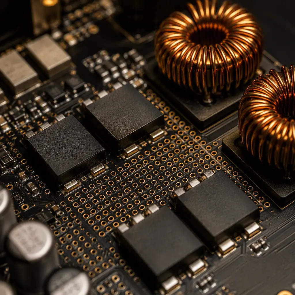
The radio is the second-worst aggressor after the amplifier. A 2.4 GHz Wi-Fi module transmitting at +18 dBm sits on the same board as microphones whose full-scale input is a few millivolts. Separation of 40 dB or more between them is a layout requirement, not a hope.
Antenna keep-out is absolute
The antenna area: usually a chip antenna or PCB trace at the board edge. Needs a keep-out zone of 10–15 mm free of copper, components and the enclosure's metal parts. The mic array must sit outside this zone; mics directly under the antenna pattern pick up the transmit burst as a loud click. Our PCB antenna guide has the keep-out rules for chip and trace antennas.
Isolate the RF module's supply and ground
Give the Wi-Fi/BT module a dedicated ground island under its footprint and a ferrite-bead-decoupled supply rail. The module's PA current pulses (hundreds of mA at the transmit burst rate) must not modulate the shared ground. The Wi-Fi 6E/7 design guide covers the 2.4 GHz grounding and decoupling details.
Plan for BT + Wi-Fi + audio scheduling
Bluetooth audio and Wi-Fi share the 2.4 GHz band; coexistence is handled by the radio stack, but the PCB must not add work: keep the BT antenna and the Wi-Fi antenna at opposite board corners, and route their RF traces with a clean ground return and no vias in the impedance-critical section. For the Bluetooth side specifically, the BLE PCB design guide covers 2.4 GHz layout.
Thermal, Mechanical and Acoustic Integration
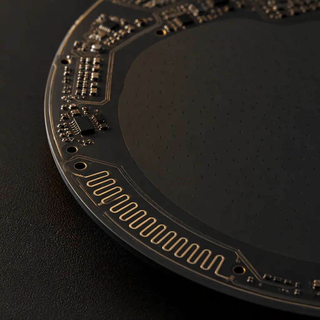
The enclosure is part of the acoustic system, and the PCB is the interface. Three integration rules prevent "it sounded fine on the bench" failures:
Seal the mic ports against internal noise
The microphone aperture on the enclosure must be gasketed or ported so that speaker pressure waves inside the cabinet do not reach the back of the mic diaphragm. The PCB layout should place the mics so their ports align with the enclosure apertures, a misaligned port acts as a Helmholtz resonator that colors the voice band.
Anchor the board to the enclosure
Screw bosses near the amplifier and near the antenna prevent microphonics, the board flexing with the bass and coupling vibration into the mics. At least three anchor points, one near the amp's thermal pad, are standard for a 20 W speaker.
Keep high components out of the acoustic path
Tall electrolytic capacitors, the Wi-Fi module and connectors cast acoustic shadows, sound waves diffract around them, changing the array's directional response. The mechanical team should define the component height limit in the acoustic chamber before layout starts.
Testing and Manufacturing for Voice Products
Voice performance must be verified at production volume, not just in the lab. A smart speaker line typically adds acoustic test stations to the standard SMT test flow:
| Test | What It Catches | Where It Runs |
|---|---|---|
| ICT / flying probe | Opens, shorts, wrong values | Post-reflow, pre-assembly |
| Mic functional test | Dead or low-sensitivity mics, port blockage | Acoustic station, sealed fixture |
| SNR / THD+N measurement | Noise coupling, hum, amp artifacts | Acoustic station, speaker loaded |
| Wake-word test | Array geometry, echo cancellation tuning | Acoustic station, reference audio |
| Wi-Fi/BT RF test | Antenna tuning, coexistence | Shielded RF chamber |
Protect the mics through SMT
MEMS mics are moisture-sensitive and their ports must stay free of solder paste and flux. Specify the mic's MSL handling (baking if needed), a stencil design that avoids paste creep into the port, and no wash step after placement if the mic is not sealed. Our MSL guide covers the handling rules, and the stencil design guide covers aperture geometry near the port.
Acoustic test with the real enclosure
SNR measured on the bare board is optimistic, the enclosure, gasket and fabric change everything. The production acoustic station should use the final enclosure in a sealed fixture with a calibrated reference speaker, measuring each mic's sensitivity and the array's wake-word performance. The inspection methods guide covers the AOI/x-ray steps that run before the acoustic station.
Archive per-unit test data
Consumer audio products rarely need serialized traceability, but batch-level records of SNR, mic sensitivity spread and RF results let you correlate field returns to production lots. For warranty analysis, keep the acoustic test logs for at least the warranty period.
Building a Smart Speaker That Users Actually Talk To
The order of design matters: fix the array geometry and the acoustic/mechanical constraints first, then partition the board around them, quiet zone for mics and codec, power zone, amp zone, radio zone, and route the audio path with the same care you would give a 40 Gbps link. Verify voice performance in the final enclosure at full volume before tooling, and repeat the acoustic test at volume in production. The products that get used are the ones that hear reliably; that reliability is manufactured, not assumed.
At Huaxing PCBA we assemble smart speaker and consumer audio boards with MSL-compliant MEMS handling, acoustic test fixtures and batch traceability across 8 SMT lines. Read our TWS earbud guide for the wearable side of voice design, or send your BOM and stackup . We'll return a DFM review covering mic port protection, antenna keep-out and amp thermal design with your quote within 24 hours.
