
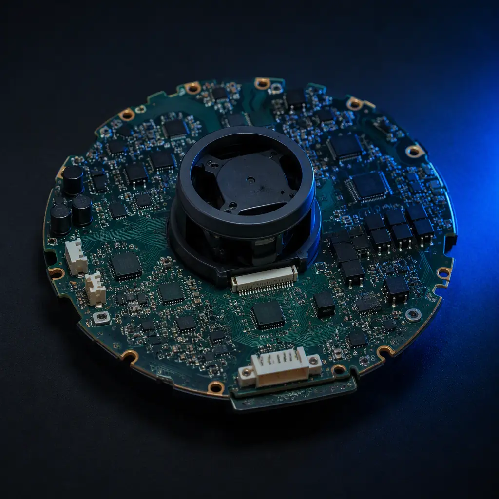
Robot vacuums are among the most sensor-dense consumer products manufactured today. A typical 2026 model carries a rotating LiDAR module, four to six cliff sensors, an IMU, two wheel-motor drivers, a suction fan controller, a battery management circuit, Wi-Fi and Bluetooth radios, and on mopping models, a water pump and mop motor — all on a 4- to 8-layer board between 0.8 and 1.6 mm thick. The layout that makes all of these coexist quietly is where the engineering is actually won.
Huaxing PCBA builds robot vacuum mainboards for consumer robotics brands — up to 8 layers with controlled impedance for the radio section, gold-plated charging contacts, selective conformal coating for mopping models, and 100% flying-probe testing before every shipment. This guide covers the design decisions that determine field reliability, the motor-drive and battery rules that prevent the classic early failures, and the manufacturing checks to put in your purchase order.
What Exactly Lives on a Robot Vacuum Mainboard?
The board is really five subsystems on one PCB: the navigation cluster, the motion cluster, the power cluster, the radio cluster, and the safety cluster. Each has different layout needs, and the conflicts between them are what make robot vacuum boards harder than they look.
| Subsystem | Typical Components | Key Layout Constraint |
|---|---|---|
| Navigation | LiDAR module, ToF/drop sensors, IMU, encoder inputs | Sensor data integrity — keep away from motor switching noise |
| Motion | 2× wheel-motor drivers, suction BLDC driver, mop motor | High-current paths with short, low-inductance loops |
| Power | BMS, charge path, DC-DC rails (3.3/5/12 V), protection | Thermal management of charge and motor surges |
| Radio | Wi-Fi/BLE SoC, antenna, RF matching | 50 Ω controlled impedance, antenna keep-out |
| Safety | Bumper sensors, drop sensors, thermal cutoffs, ESD | Fail-safe wiring — sensors must read correctly under fault |
The board shape is also unusual: circular, with the LiDAR turret occupying the center, the battery pack wrapped around the outside, and the wheel motors on opposite sides. That geometry forces routing around a center keep-out and puts the highest-current traces on the outer ring — both worth planning in the stackup before layout starts. Our stackup design guide covers how to allocate layers when a single board carries analog sensors, switching power and a radio.
Navigation Sensing: LiDAR, ToF, and Cliff Sensors
A robot vacuum navigates with three complementary sensor families, and each one has a PCB-side requirement that is easy to miss.
Keep LiDAR Data Lines Away From Motor Switching
The rotating LiDAR module spins at 2,000–3,000 RPM and streams point-cloud data over a serial link to the main SoC. The wheel motors and suction fan switch tens of amps within centimeters of that link. Route LiDAR data lines as differential pairs with a solid reference plane, and keep them off the layers directly above motor-driver outputs. Our signal integrity guide has the pair-routing rules.
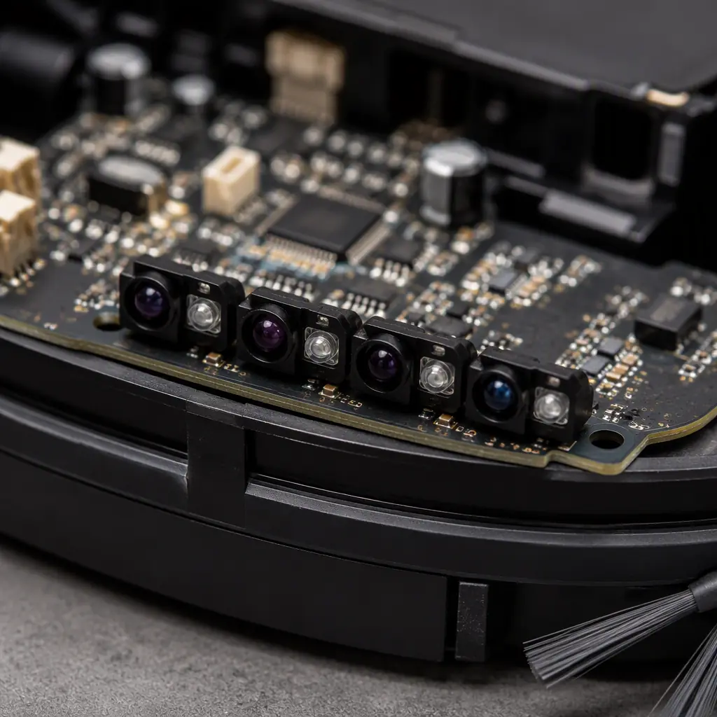
Cliff Sensors Work by IR Reflection — the Board Must Not Blind Them
Cliff (drop) sensors are infrared emitter-receiver pairs aimed at the floor, typically four to six around the chassis. They detect a stair edge when the reflected signal drops below a threshold. Solder mask color, silkscreen ink, and even a component shadow in the sensor field of view can shift the calibration. Keep the sensor zone clean of copper and ink, and specify matte mask on the sensor side to avoid specular reflections. Our solder mask guide explains the reflectivity differences between gloss and matte finishes.
Give the IMU a Quiet Mechanical and Electrical Home
The IMU provides odometry dead-reckoning between LiDAR scans. Place it near the board center — the same spot where the LiDAR turret sits, so in practice it lands beside the turret — with solid ground pour underneath and no switching regulators within a few millimeters. A gyro that picks up 20 kHz motor noise produces drift that looks like a navigation bug. Our MEMS sensor design guide covers the grounding and isolation rules in detail.
Key Takeaway: Navigation failures are the #1 reason robot vacuums are returned. Most are not software bugs — they are EMI coupling into LiDAR data, IMU drift from regulator noise, or cliff sensors blinded by the board's own mask and ink. Treat the sensor cluster like an analog front end, not a digital peripheral.
Motor Drive: Stall Currents, PWM Frequency, and Audible Noise
A robot vacuum has three motor stages with very different electrical personalities. Sizing the drive correctly for each one is the difference between a board that lasts and one that comes back with a blown MOSFET.
| Motor Stage | Typical Power | Drive Voltage | Failure Mode to Design For |
|---|---|---|---|
| Wheel motors (2×) | 5–15 W each | 12–21.6 V | Stall against furniture — 2–3× rated current |
| Suction fan (BLDC) | 10–30 W | 12–21.6 V | Blocked airflow, carpet drag, inrush |
| Mop motor / pump | 2–8 W | 5–12 V | Dry-run, water ingress on the driver |
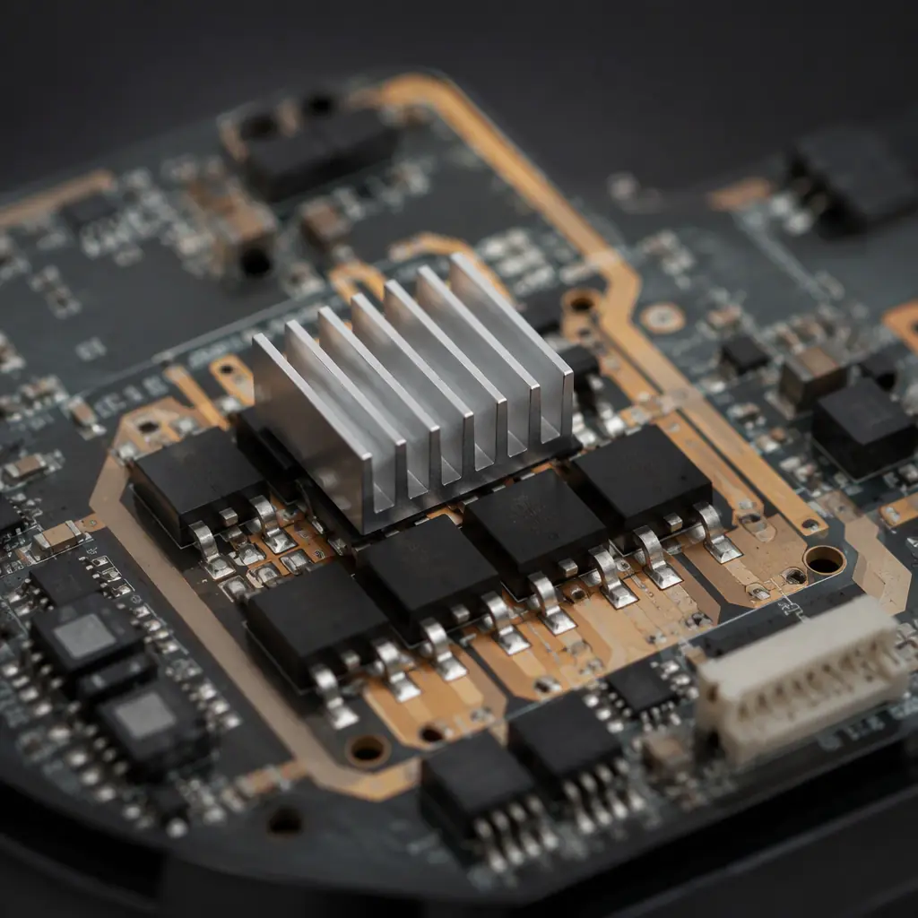
Size MOSFETs for Stall Current, Not Running Current
A wheel motor that draws 1.5 A free-running can pull 3–4.5 A when the robot pushes into a chair leg. Select the low-side MOSFETs and sense resistors for the stalled condition with margin, and let the firmware current-limit below the hardware limit. Verify the PCB copper can carry the stall current: at 4.5 A continuous, a 1 oz trace needs roughly 3.5 mm width before derating — plan the motor loop in the stackup, not as an afterthought. Our trace width and current capacity guide has the IPC-2152 tables.
Run PWM Above 20 kHz — Audible Noise Is a Return Reason
Motor PWM below 20 kHz produces an audible whine that customers hear across the room and return the unit over. Standard practice in 2026 robot vacuums is PWM at 20–40 kHz for wheel and suction motors, which pushes the fundamental above human hearing. The trade-off is higher switching losses in the MOSFETs — acceptable at these power levels, but it means the driver layout needs a tight gate-drive loop and adequate copper. Our power electronics PCB guide covers gate-drive layout and snubber design.
Add Flyback and Bulk Decoupling at Every Motor Connector
Each brushed motor connector needs a flyback diode (or TVS for faster decay) and a bulk capacitor local to the connector, not shared across the board. The wheel motors on a robot vacuum start and stop hundreds of times per cleaning cycle; without local decoupling, the current spikes modulate the 12 V rail and corrupt the IMU and radio. Our power integrity guide explains rail-modulation control in depth.
Battery, BMS, and the Charging Dock
The battery subsystem is where robot vacuum economics bite: the pack is a large fraction of the BOM, and the charging path sees daily mechanical wear that ordinary consumer electronics never experiences.
Typical Packs: 4S at 14.4 V, Up to 6S at 21.6 V
Most robot vacuums run a 4S Li-ion pack at 14.4 V nominal with 2,500–5,200 mAh cells, or a 6S pack at 21.6 V on higher-suction flagships. The BMS must cover over-voltage, under-voltage, over-current, and over-temperature per cell, plus cell balancing. Specify a BMS with cell-balance current of at least 50 mA so the pack stays balanced through hundreds of partial charge cycles — imbalance is a leading cause of early pack failure in robots that dock for a top-up after every run. Our BMS PCB guide covers protection and balancing design in detail.
Charging Contacts Wear Mechanically — Plan the Metallurgy
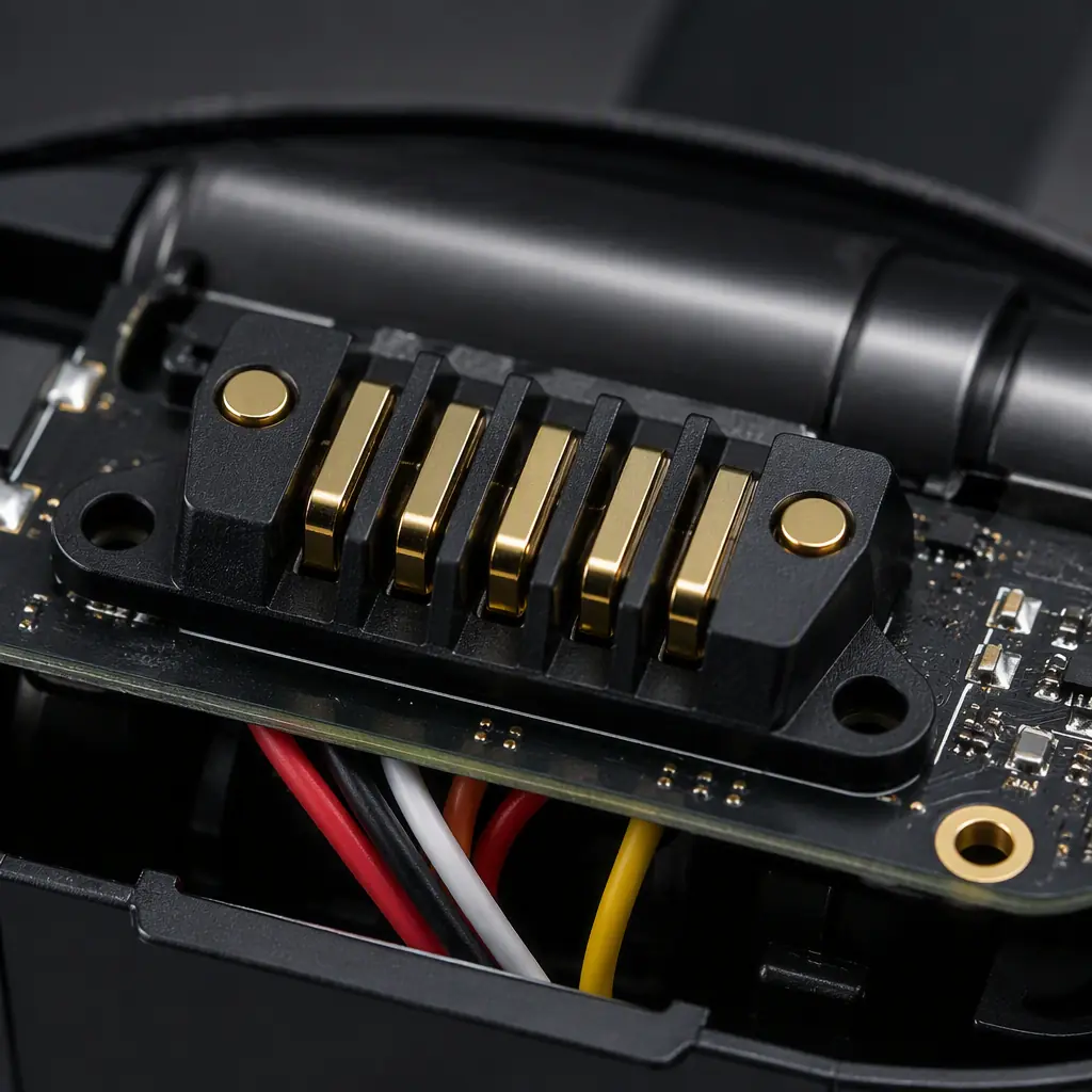
The robot docks daily, making and breaking the charging contact hundreds of times per year. Specify gold-plated contacts (hard gold over nickel, 0.1–0.3 µm gold minimum) on both the robot and the dock, and design the contact pads large enough to tolerate misalignment. On the PCB side, that means a robust pad geometry with the plating called out on the fabrication drawing. Our gold plating guide explains hard-gold vs ENIG trade-offs for contact applications.
Wireless Charging Variants Change the Layout Entirely
Flagship models are moving to wireless charging docks, which replaces the contact pads with a receiver coil and its rectifier stage. The coil needs a large clean area, the rectifier needs thermal relief, and the whole power path needs to handle 15–30 W inductively. If your roadmap includes a wireless-charging SKU, reserve the coil zone in the stackup from day one. Our wireless power transfer guide covers coil layout and rectifier design.
Mopping Models: Water, Conformal Coating, and IP Ratings
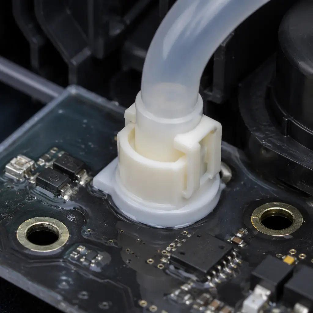
Once a robot carries a water tank, the board is no longer a dry electronics product. The classic failure is not a flood — it is years of micro-condensation inside a warm chassis slowly corroding exposed traces and connector pins.
Specify Selective Conformal Coating, Not Full Coverage
Mopping models should have acrylic conformal coating applied selectively — covering the analog sensor area, the BMS, and the motor drivers, while leaving connectors, charging contacts, and test points uncoated. Full coverage coats the test points and makes rework nearly impossible. Our conformal coating guide covers acrylic vs silicone vs Parylene selection for moisture environments.
Design the Water Path: Pump Below the Board, Drips Away From Vents
The pump and water lines should sit below the mainboard plane so any leak drips away from electronics, and the board's mounting bosses should be on standoffs rather than sitting flush. Even with coating, a board that lives in the drip path will fail eventually — the mechanical layout is the primary defense, the coating is the secondary one.
Target IPX4 at the System Level, But Don't Stop There
Most mopping robots target IPX4 (splash-proof) at system level, which the sealed chassis provides. The board itself should be rated to tolerate condensation: coated, with conformal-coated connector solder joints on the water-side connectors, and connector pins specified with gold or tin-lead finishes that resist fretting corrosion. Our ionic contamination guide covers why cleanliness levels matter before coating.
EMI and Noise: Why Quiet Boards Ship More Units
Robot vacuums fail EMC testing surprisingly often, for a consistent reason: a 20–40 kHz switching motor system sharing a board with a 2.4 GHz radio and a sub-millimeter-precision IMU. The emissions budget has to be managed in the layout, not at the compliance lab.
Give the Radio Its Own Clean Corner
Place the Wi-Fi/BLE SoC and its antenna at the board edge farthest from the motor connectors, with a keep-out around the antenna per the module vendor's drawing. The 2.4 GHz band is exactly where motor-switching harmonics land, so the antenna feed needs controlled impedance and the radio ground needs a continuous reference. Our RF PCB guide covers antenna feed and grounding practice.
Plan the Emissions Budget Like a Product Spec
Decide at kickoff whether the product targets FCC Part 15B, CE (EN 55014 for household appliances), or both, and carry the margin into the layout: keep 6 dB of headroom on radiated emissions, which usually means ferrite beads on motor cables, a continuous chassis ground, and shield cans over the noisiest drivers. Our EMI/EMC design guide has the full emissions-control checklist.
Test Emissions With Motors Running, Not Just Idle
The classic lab surprise: the board passes with the motors unplugged and fails by 8 dB with the suction fan at full speed. Your manufacturing partner should support pre-compliance testing with the actual motor load connected. Put "EMC pre-scan with motor load" in the project plan, not in the re-spin budget. Our EMC compliance guide walks through specifying this to your manufacturer.
Assembly and Reliability for a 2-Year Consumer Warranty
The design rules above prevent field failures; the assembly rules below make sure the failures that do happen are caught before shipment. Robot vacuums are consumer products with a brutal duty cycle — daily operation, vibration, and temperature cycling — so the manufacturing checks are stricter than a typical consumer board.
100% Flying Probe or ICT on Every Board
With the BMS, motor drivers, and charging path all safety-relevant, a sample-test strategy is not acceptable. Require 100% electrical test — flying probe for prototype and low volume, ICT with a bed-of-nails fixture once volumes justify the tooling. The test program must verify the BMS protection thresholds, not just connectivity. Our flying probe vs ICT guide covers when to switch.
Burn-In and Thermal Cycling Catch the Early Failures
Consumer robots fail in the first month when marginal solder joints and weak components surface under thermal cycling. Specify a 2–4 hour burn-in with power cycling for production boards, and a thermal-cycling sample per lot (e.g., 100 cycles from 0 to 60 °C). Our burn-in and ESS guide has the test profiles, and the thermal cycling guide covers IPC-9701 requirements.
ESD Control Through the Whole Assembly Chain
Robot vacuum boards carry sensitive IMUs, LiDAR interfaces, and RF front ends. Require an ANSI/ESD S20.20-compliant assembly line — grounded workstations, ionizers, and ESD-safe packaging for shipment. A board zapped during handling can ship with a degraded IMU that reads fine at ICT but drifts in the field. Our ESD control program guide is the audit checklist.
Summary: The Robot Vacuum Board Checklist
A robot vacuum mainboard that survives the field treats the navigation cluster as a precision analog front end, sizes the motor drive for stall currents, protects the battery path with a real BMS and gold-plated contacts, waterproofs the mopping variants selectively, and manages EMI as a product spec from day one. None of it is exotic — it is disciplined mixed-signal layout backed by manufacturing checks that match the duty cycle.
At Huaxing PCBA we manufacture robot vacuum mainboards up to 8 layers with controlled impedance, hard-gold charging contacts, selective conformal coating, and 100% flying-probe test on every board. Our DFM review checks the sensor-zone clearance, motor-loop layout, BMS test coverage, and coating mask before tooling. Read our robotics PCB guide to prepare your design, or send your files for a free DFM review and quote.
