
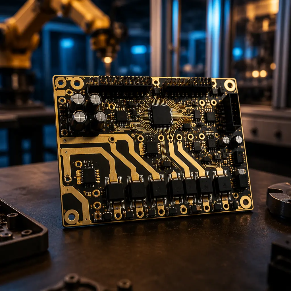
The global industrial robotics PCB market is expanding rapidly as factories deploy collaborative robots (cobots), autonomous mobile robots (AMRs), and smart servo systems. A single six-axis robot arm contains 8-15 distinct PCBs . Motor driver boards, encoder interface boards, safety controller boards, power distribution boards, and a main compute module. Each board type has unique electrical, thermal, and mechanical requirements that procurement engineers must specify correctly at the RFQ stage.
Huaxing PCBA manufactures the full range of robotics PCBs at our 15,000 m² Shenzhen facility: heavy copper motor driver boards up to 6oz, high-density encoder interface boards with 0201 passives, and rigid-flex harness interconnect boards for articulated robot joints. With IATF 16949 certification and IPC Class 3 assembly as standard on industrial boards, we support robotics OEMs scaling from prototype to 10,000-unit annual production.
Motor Driver PCB Design for Servo and Stepper Control
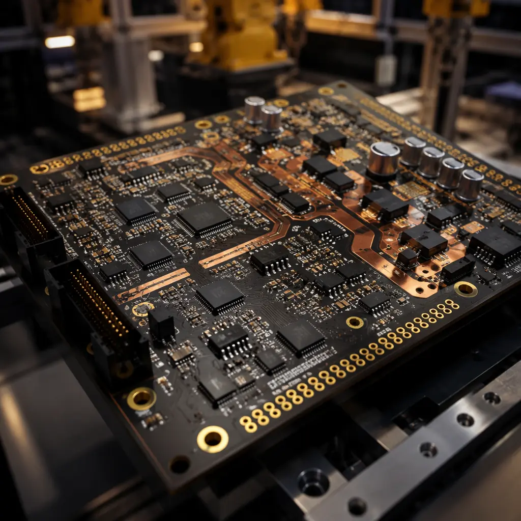
Motor driver boards are the power workhorses of any robot system. A single servo drive board may switch 48V at 20A continuous through its MOSFET H-bridge, generating 15-30W of heat that must be dissipated through the PCB itself. The design rules are unforgiving: one undersized trace or insufficient copper pour, and the board fails under thermal cycling within months.
Heavy Copper for High-Current Motor Phases
Motor phase traces carry 10-30A continuous with 2-3× inrush peaks. 2oz copper is the minimum for any robotics motor driver; 4oz-6oz inner and outer layers are standard for industrial servo drives above 500W. Our copper weight selection guide covers the manufacturing considerations: wider trace spacing for etching undercut, larger annular rings for thermal stress, and the cost step from 2oz to 6oz.
Creepage and Clearance for 48V-400V Bus Voltages
Industrial robots operate on DC bus voltages from 24V (small cobots) to 400V (large industrial arms). IEC 61800-5-1 requires minimum 3.0mm creepage for 400V polluted-degree-2 environments. This often forces a larger PCB form factor than the electrical design alone would dictate. Our high-voltage PCB design guide explains the spacing rules that prevent arc-over in humid factory conditions.
Thermal Via Fields Under Power MOSFETs and Gate Drivers
Each power MOSFET in a three-phase inverter dissipates 2-5W. A dense thermal via array (0.3mm pitch, filled and capped) under each MOSFET package carries heat into internal copper planes. Without these vias, junction temperatures exceed 150°C within minutes of full-load operation. See our thermal management guide for via density calculations.
Factory Reality: The #1 field failure mode in robotics motor drivers is not component failure. It is PCB delamination under the power MOSFETs after 6-12 months of thermal cycling. Specifying high-Tg laminate (Tg ≥ 170°C) and 4oz+ copper on power layers eliminates this failure mode entirely. The material cost difference is under $3 per board.
Sensor Integration and Mixed-Signal Layout
A modern collaborative robot integrates 6-12 sensor types: motor encoders (incremental and absolute), torque sensors in each joint, IMUs for orientation sensing, time-of-flight or LiDAR for environment mapping, force-torque sensors at the end effector, and camera modules for vision-guided motion. Each sensor type imposes different PCB design constraints.
Isolate Analog Sensor Front-Ends from PWM Noise
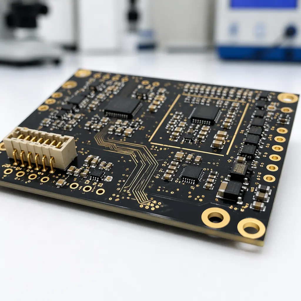
Motor PWM switching at 8-20 kHz injects broadband noise into ground planes. High-resolution encoder signals (20-bit absolute encoders) require an analog front-end SNR above 80 dB. Physical separation (≥ 10mm) between the analog sensor section and the PWM power stage, combined with split ground planes connected at a single star point, prevents noise coupling. Our mixed-signal PCB design guide covers ground partitioning strategies.
Differential Pair Routing for Encoder and Communication Buses
RS-485, CAN FD, and EtherCAT communication between robot joints demand controlled-impedance differential pairs with ±5% tolerance. A single impedance discontinuity on an EtherCAT line can cause packet loss that triggers an emergency stop. Our impedance control guide details the stackup and trace geometry for 100Ω and 120Ω differential pairs.
Vibration Resistance and Mechanical Reliability
Industrial robots subject their internal PCBs to continuous vibration at 5-500 Hz with acceleration up to 5g in fast pick-and-place applications. Connectors, BGA packages, and large ceramic capacitors are the three most common vibration-induced failure points.
Conformal Coating for Dust, Oil Mist, and Humidity
Factory-floor robots operate in environments with airborne cutting oil mist, metal dust, and 60-95% humidity. Conformal coating (acrylic, silicone, or parylene per IPC-CC-830) prevents dendritic growth between closely spaced pads. Our conformal coating guide covers material selection by chemical exposure.
Underfill for BGA and Large QFN Packages
Vibration concentrates stress at the corners of BGA and large QFN solder joints. Corner underfill (epoxy dispensed along two edges of the package) increases vibration lifetime by 5-10× at a cost of $0.30-0.80 per component. Specifying underfill at the assembly stage is far cheaper than field-replacing a failed robot controller board.
Rigid-Flex for Articulated Joint Interconnects
Robots with rotating joints (axis 4, 5, 6 of a six-axis arm) benefit from rigid-flex PCBs that eliminate the connector failure point in the harness. A single rigid-flex board carries power, encoder signals, and communication buses through the joint with 10× fewer connector mating cycles to fail. Our rigid-flex PCB guide covers bend radius and layer stack design.
Procurement Insight: The BOM cost difference between a consumer-grade robotics PCB and an industrial-grade one is typically 25-40%. But the warranty return rate difference is 10-20×. For robotics OEMs selling $30,000+ systems with 3-year warranties, specifying IPC Class 3 assembly with conformal coating and underfill is not an option, it is the minimum viable quality standard.
Summary: Specifying Robotics PCBs That Survive the Factory Floor
Robotics PCB procurement requires attention to four dimensions that consumer electronics PCBs never face: high-current motor traces (2oz-6oz copper), mixed-signal isolation between PWM power stages and precision sensors, vibration resistance (underfill, conformal coating, rigid-flex interconnects), and extended temperature range (-40°C to +105°C ambient in un-air-conditioned factories).
At Huaxing PCBA, we manufacture the complete range of robotics PCBs, from 2-layer power distribution boards to 16-layer main compute modules with blind and buried vias. Our 8 SMT lines handle 0201 passives and 0.3mm pitch BGA packages with 100% AOI and X-Ray inspection as standard. Engineering samples ship in 24-48 hours. Read our testing methods comparison or contact our engineering team with your robotics PCB requirements.
