
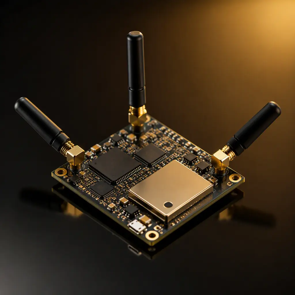
A modern IoT positioning module is a small board with a big job: it must receive GNSS satellite signals outdoors, exchange UWB time-of-flight pulses indoors, and listen for BLE direction-finding (AoA/AoD) beacons, all simultaneously, on a PCB that fits inside an asset tag the size of a credit card. Each radio has different frequency, sensitivity and antenna requirements, and they share a board only 30×40 mm in many designs.
This is the class of hardware behind warehouse RTLS, tool tracking, patient wandering alarms and fleet asset monitoring. And its failure mode is rarely the radio itself. It is almost always the board: antennas too close, power noise from the UWB pulse currents, or a GNSS feed starved by a noisy supply. Huaxing PCBA assembles positioning modules for 40+ IoT customers, and this guide covers the layout decisions that determine whether your module actually positions or just beeps.

The Three-Radio Problem: Frequencies, Sensitivities and Antennas
Before any layout work, understand what each radio needs. They are not equally forgiving, and their requirements often conflict:
| Radio | Band | Typical Sensitivity | Critical Requirement |
|---|---|---|---|
| GNSS (L1) | 1575.42 MHz | -165 dBm tracking | Clean ground plane under antenna; no digital noise |
| UWB (CH9) | 6.5–8 GHz | -90 dBm | Phase-center stability; precise antenna placement |
| BLE (2.4 GHz) | 2.400–2.483 GHz | -96 dBm | AoA antenna array phase accuracy |
The GNSS receiver is the most sensitive radio on the module, it tracks signals 20 dB below the noise floor of a typical digital board. The UWB radio is the most brutal neighbor, its pulse transmissions draw 100–300 mA current spikes at microsecond scale. The BLE AoA function is the most geometrically demanding, it measures phase differences between antennas, so any asymmetry in the array corrupts the angle estimate. See our GNSS receiver PCB guide and UWB design guide for each radio's deep-dive.
Key Takeaway: Treat the three radios as one system with conflicting needs, not three independent circuits. The board-level decisions, antenna separation, ground partitioning, supply isolation, matter more than any single radio's reference design.
Antenna Placement: The Board's Most Expensive Real Estate
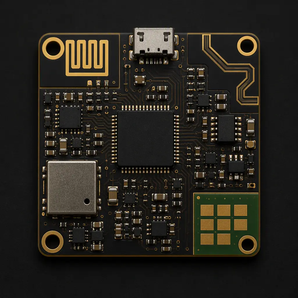
Antenna separation is the first constraint. Two antennas on one small board couple through near-field and conducted paths, and the coupling directly degrades the weaker receiver. Minimum practical separation on a 30×40 mm module is 10–15 mm edge-to-edge, which forces a corner antenna arrangement: GNSS at one corner, UWB at the opposite, BLE array along a third edge.
GNSS antenna: corner + full ground plane beneath
The GNSS antenna needs a continuous ground plane of at least 25×25 mm beneath it, the ground plane is half the antenna. Keep all digital traces and power planes at least 3 mm away from the antenna clearance zone. Our antenna design guide covers feed-line and clearance rules in detail.
UWB antenna: phase-center stability
UWB ranging accuracy depends on the antenna's phase center staying fixed. Vias, pads or copper fills near the UWB antenna feed shift the phase center with frequency, keep the antenna area clean and symmetric. For anchor designs (fixed receivers), consider a chip antenna with a datasheet ground keep-out; for tags, a PCB monopole is common.
BLE AoA array: symmetry is the spec
BLE direction-finding uses an antenna array (typically 2–8 elements) and measures phase differences. Every element must see identical surroundings: same ground clearance, same trace length to the switch, no copper asymmetry. A 0.5 mm asymmetry in element placement can shift the angle estimate by several degrees.
RF Coexistence: Keeping UWB Pulses Out of the GNSS Front End
UWB transmissions at 6.5–8 GHz can desensitize the GNSS receiver through two paths: radiated coupling and conducted noise on shared supplies. On a module with all three radios, coexistence is a power and layout problem as much as a frequency problem.
Isolate the RF supplies
Give the GNSS front end its own LDO, fed from a point far from the UWB PA supply. A shared regulator lets UWB pulse currents modulate the GNSS supply rail, and that noise lands directly in the L1 band. Ferrite beads plus 10 µF bulk and 100 nF ceramic on each RF rail are the minimum.
Time-division scheduling in firmware
UWB and GNSS do not need to transmit and track simultaneously in most asset-tracking use cases. A firmware schedule that pauses UWB bursts during GNSS acquisition windows is the cheapest coexistence fix. It costs nothing in BOM and eliminates the worst interference case. Our BLE PCB design guide discusses similar coexistence scheduling.
Ground stitching between RF zones
Partition the ground plane into radio zones connected by a single-point bridge or dense via stitching along the partition line. This contains return currents and prevents UWB pulse currents from flowing under the GNSS antenna. Stitching vias every 1–2 mm along the boundary is the standard practice.
Power Integrity for Pulse-Current Loads
A UWB transceiver draws 100–300 mA in short bursts; the GNSS receiver draws 20–30 mA continuous; the BLE radio draws 5–15 mA average with 2.4 GHz switching. The power delivery network must keep all three rails stable while the UWB pulses. Two decisions dominate:
Bulk capacitance near the UWB PA
The UWB PA needs local energy storage within 3–5 mm of its supply pin: a 10 µF ceramic plus 100 nF and 10 nF in decreasing sizes. The loop from PA to capacitor must be short and wide, this is where ground bounce becomes GNSS noise.
Separate AGND/DGND with a defined bridge
Analog and digital grounds meet at a single point near the module's input connector. Keep the GNSS RF return currents on the analog side and digital return currents on the digital side. A common mistake is a solid ground plane that lets digital noise circulate under the RF front end. Our power electronics PCB guide covers plane partitioning in depth.
Manufacturing and Testing Positioning Modules at Scale
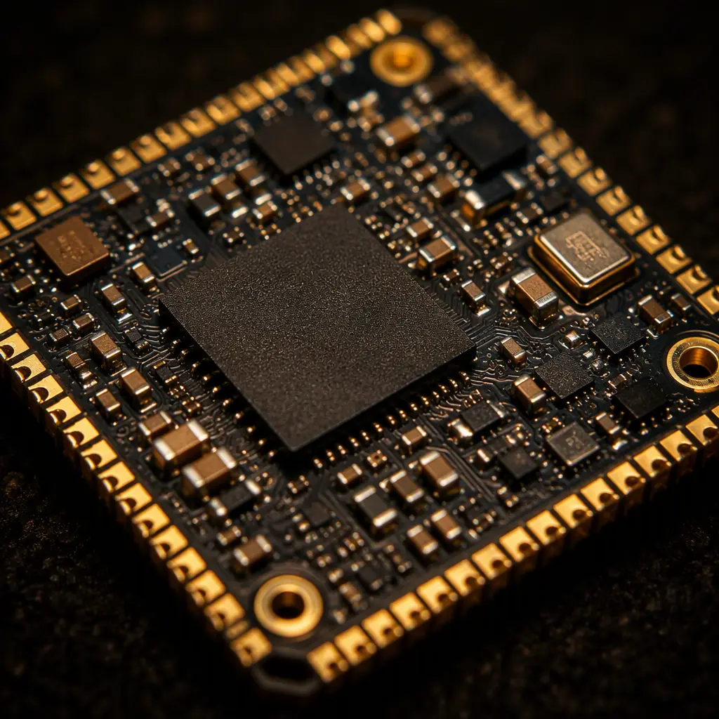
Positioning modules carry three radios, multiple antennas and fine-pitch components on a small board, a combination that demands specific manufacturing and test attention.
RF testing per radio
Every module needs an RF test at production: GNSS sensitivity (or at least a conducted power/SNR check), UWB TWR round-trip time verification, and BLE RSSI/phase sanity. A shielded test fixture with three antenna ports is standard. Our testing methods guide compares the options.
X-ray for BGA and module stacking
Positioning modules often use the radio SoC as a BGA and sometimes stack a second module (e.g., GNSS module on UWB module). X-ray inspection verifies BGA solder joints that AOI cannot see. Our BGA assembly guide covers X-ray acceptance criteria.
Conformal coating for industrial tags
Asset tags live in warehouses, vehicles and outdoor yards. Conformal coating protects the module from humidity and condensation. But coating near antennas can detune them, so masked zones or coating thickness control is required. Our conformal coating guide details the options.
Reliability Reality: A positioning module with three radios has roughly three times the potential failure points of a single-radio board. Production RF testing is not optional. It is the difference between shipping a tag that positions in the field and a tag that needs a firmware update nobody can install.
Summary: The Positioning Module Checklist
Design a positioning module as a system: corner antennas with 10–15 mm separation, GNSS ground plane preserved, UWB supply isolated with local bulk capacitance, BLE array kept symmetric, and RF test coverage for all three radios in production. The layout decisions are interdependent, change one antenna position and you re-validate the whole coexistence budget.
At Huaxing PCBA, we assemble multi-radio positioning modules with 0201 components and 0.3 mm pitch BGAs across 8 SMT lines, with RF test fixtures built per product and X-ray inspection on every BGA joint. Our engineering team reviews antenna clearances and supply partitioning during the free DFM check. Read our cellular IoT module guide for the connectivity side of IoT hardware, or contact us with your positioning module design for a manufacturing review.
