
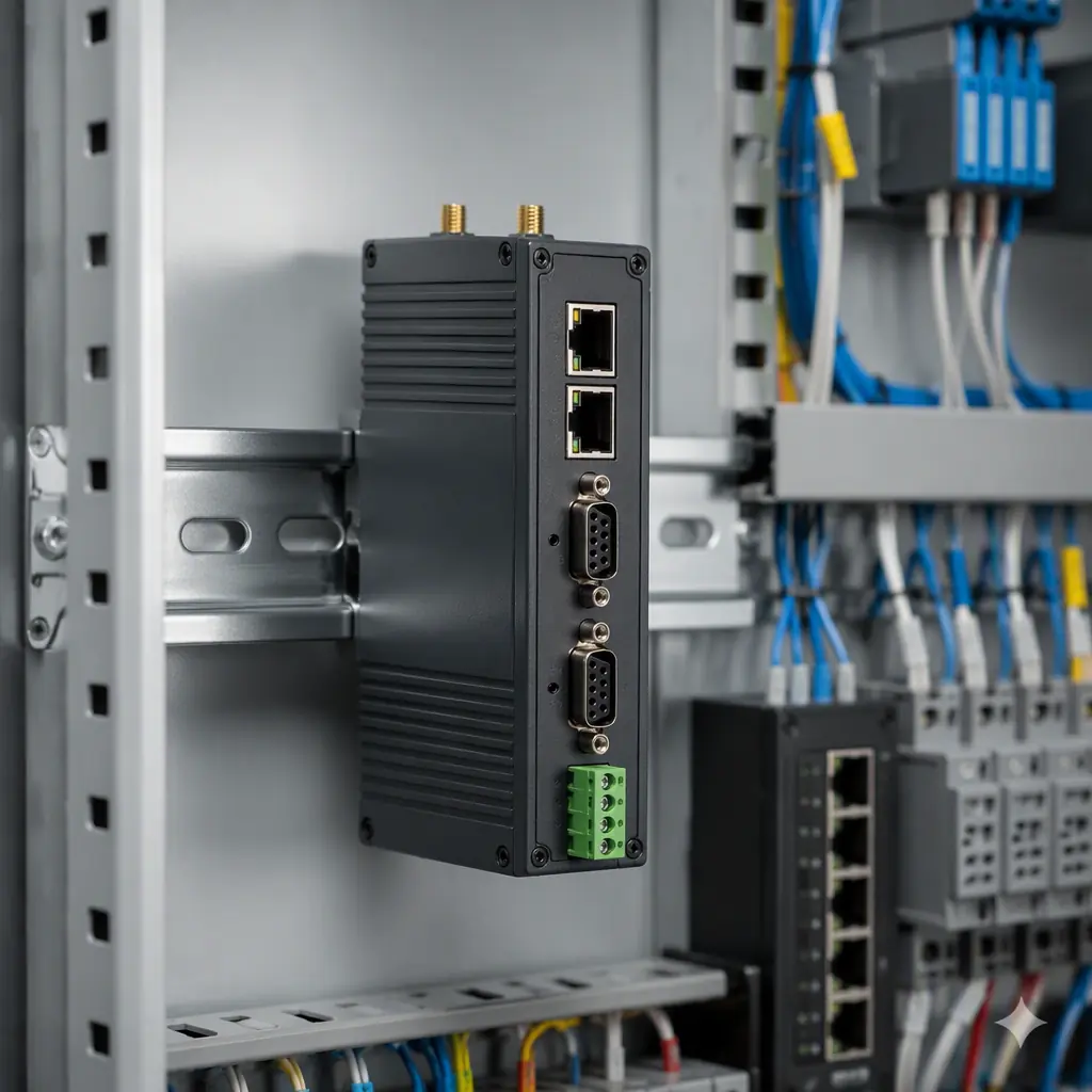
An IIoT edge gateway is the translator between an old, dirty, proprietary factory floor and the modern cloud. It has to aggregate data from machines that speak dozens of mutually incompatible protocols, process it locally, and push it up to a server, reliably, in an environment that eats consumer electronics for breakfast. It is one of the most demanding devices in the industrial catalog, and it is usually under-designed.
At Huaxing PCBA we build industrial boards from 2 to 32 layers with IATF 16949 and ISO 9001 quality systems, so we understand the mixed-signal, multi-domain challenge of a gateway board.
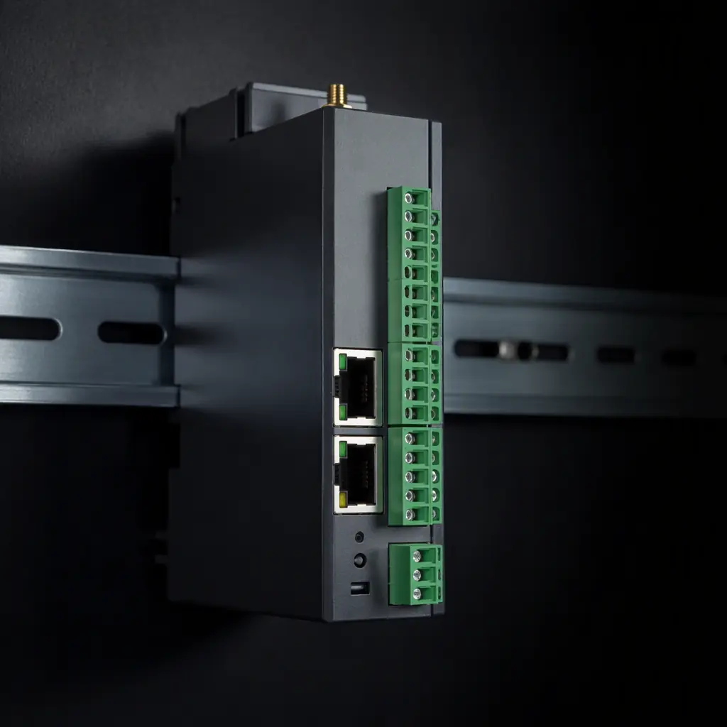
What an Edge Gateway Actually Has to Do
Before any layout decision matters, it helps to be precise about the gateway's job. It is not a router, and it is not a server. It is a real-time protocol bridge with some local compute.
Protocol Conversion
The gateway must natively speak the fieldbus protocols the installed base uses. Modbus RTU/TCP, PROFINET, EtherCAT, CANopen and RS-485 are the common ones. Each has its own PHY, timing, isolation and EMC requirement. This is the hardest part of the design because you are mixing several distinct electrical domains on one board. See our RS-485/RS-232 design guide and industrial Ethernet design guide for the port-level details.
Edge Compute
Some filtering, normalization and decision-making happens on the gateway itself rather than in the cloud. This needs an application processor: often a SoM (system-on-module) to avoid a long bring-up, or a discrete SoC to minimize cost and footprint. The choice of compute platform determines most of the board's layer count and density. See our SoM carrier board design guide.
Connectivity Uplink
Data has to leave the plant. The gateway typically has an Ethernet uplink and/or a cellular modem (4G/5G) for sites without wired backhaul. This adds a radio sub-system to what is already a dense mixed-signal board. See our cellular module design guide for the antenna and RF requirements.
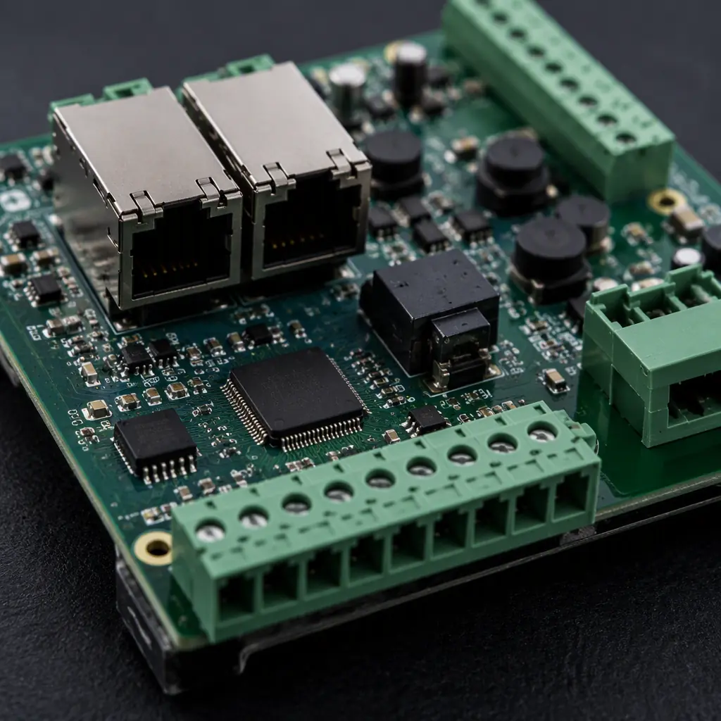
Wide-Voltage Input and Power Protection
Industrial power is not a clean 24 V rail. It is an unregulated supply that can swing from 18 V to 60 V, with transients and surges. The board must accept a wide input and survive faults.
Wide-Range Input Stage
A gateway should accept a 9-36 V or wider DC input. This requires a buck converter that can handle the full range plus input ripple, with a proper thermal budget. The input stage needs a surge-suppression device (TVS) and a polyfuse for protection. Our power electronics guide covers the converter design.
Surge and Transient Protection
Surges from motor switching or lightning are a real hazard in a plant. Every externally-accessible port, power, Ethernet, RS-485, digital IO, needs protection against the relevant standard (IEC 61000-4-4 and 61000-4-5 for EFT and surge). This is where a gateway earns its price premium. See our EMC compliance guide for the protection topology.
Isolation Between Domains
Fieldbus interfaces like RS-485 often need galvanic isolation from the CPU to break ground loops, which is a common source of intermittent factory-floor failures. The isolation barrier must be carefully laid out, keep the isolated and non-isolated parts of a domain physically separate. Our mixed-signal design guide covers the isolation discipline.
| Interface | Key Requirement | Design Note |
|---|---|---|
| RS-485 | Galvanic isolation, ESD | Termination, shielded pair, TVS on port |
| Ethernet | Magnetics, ESD | Keep PHY near port, controlled differential pair |
| Cellular | 50Ω RF, antenna keep-out | Match antenna, shield RF from fieldbus |
| Digital IO | Optocoupler/solid-state relay isolation | Separate IO bank from processor |
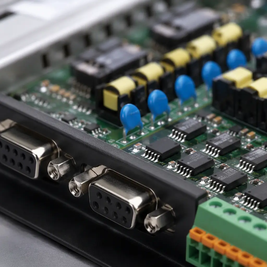
Routing and Layout for a Multi-Protocol Board
Once the power and isolation domains are settled, the layout is what separates a gateway that works from one that fails intermittently in the field. The guiding theme is domain separation and controlled routing for the high-speed links.
Controlled Impedance for Ethernet and RF
The Ethernet differential pairs must be routed at 100 Ω differential impedance, and the cellular antenna feed at 50 Ω single-ended. This requires a proper stackup and careful routing. See our impedance control guide and stackup design guide.
Keep-Out Zones and Antenna Placements
The cellular antenna needs a clean keep-out area with no copper or reference-plane interruption, and it should be far from the fieldbus ports. A poorly-placed antenna kills range. See our RF PCB design guide.
Grounding and Shielding
The board needs a solid reference plane, and the fieldbus ports typically require a shielded connector tied to chassis. Grounding strategy is the difference between a robust and a flaky design. See our EMI/EMC design guide for how to ground the I/O.
Thermal Design for an Enclosed DIN-Rail Box
A DIN-rail device is mounted in a sealed plastic enclosure with no fan. All heat leaves by conduction through the board and the chassis. The processor, the power stage and the modem are the main heat sources, and they must be planned for in the layout, see our thermal management guide for the approach.
Ruggedization and Qualification
An industrial gateway is often purchased for a 10-year service life in harsh conditions. That means a ruggedization and qualification plan, not just a good layout.
Wide-Temperature Operation
Components must be specified for the operating range, often -40 °C to +85 °C. Cheap consumer-graded capacitors and connectors will fail. Electrical and thermal cycling testing is essential, see our thermal cycling testing guide.
Vibration, Shock and Conformal Coating
The DIN-rail mount and the environment subject the board to vibration. Heavy parts need anchoring and the board should be coated against moisture. Our vibration and shock testing guide and conformal coating guide cover the qual.
Burn-In and ESD Qualification
Given the cost of a field failure, burn-in and a full ESD qualification are worthwhile. See our burn-in and ESS guide and ESD control guide.
Summary, Building an Edge Gateway That Lasts
An IIoT edge gateway is a multi-domain, ruggedized industrial device. Start from the power and isolation domains, plan the compute module and the radio sub-system, route the high-speed links at controlled impedance, and protect every external port. Then qualify for wide temperature, vibration and moisture, and burn-in the production units. A gateway designed this way will outlive the machines it connects.
At Huaxing PCBA we build multi-domain industrial boards from 2 to 32 layers with controlled-impedance routing and IPC Class 2/3 acceptance, backed by IATF 16949 and ISO 9001 quality systems. We offer a free DFM review on the power, isolation, and EMC design of your gateway board, so it passes factory-floor qualification cleanly. Send your files for a quote or talk to an engineer about your industrial gateway PCB.
