
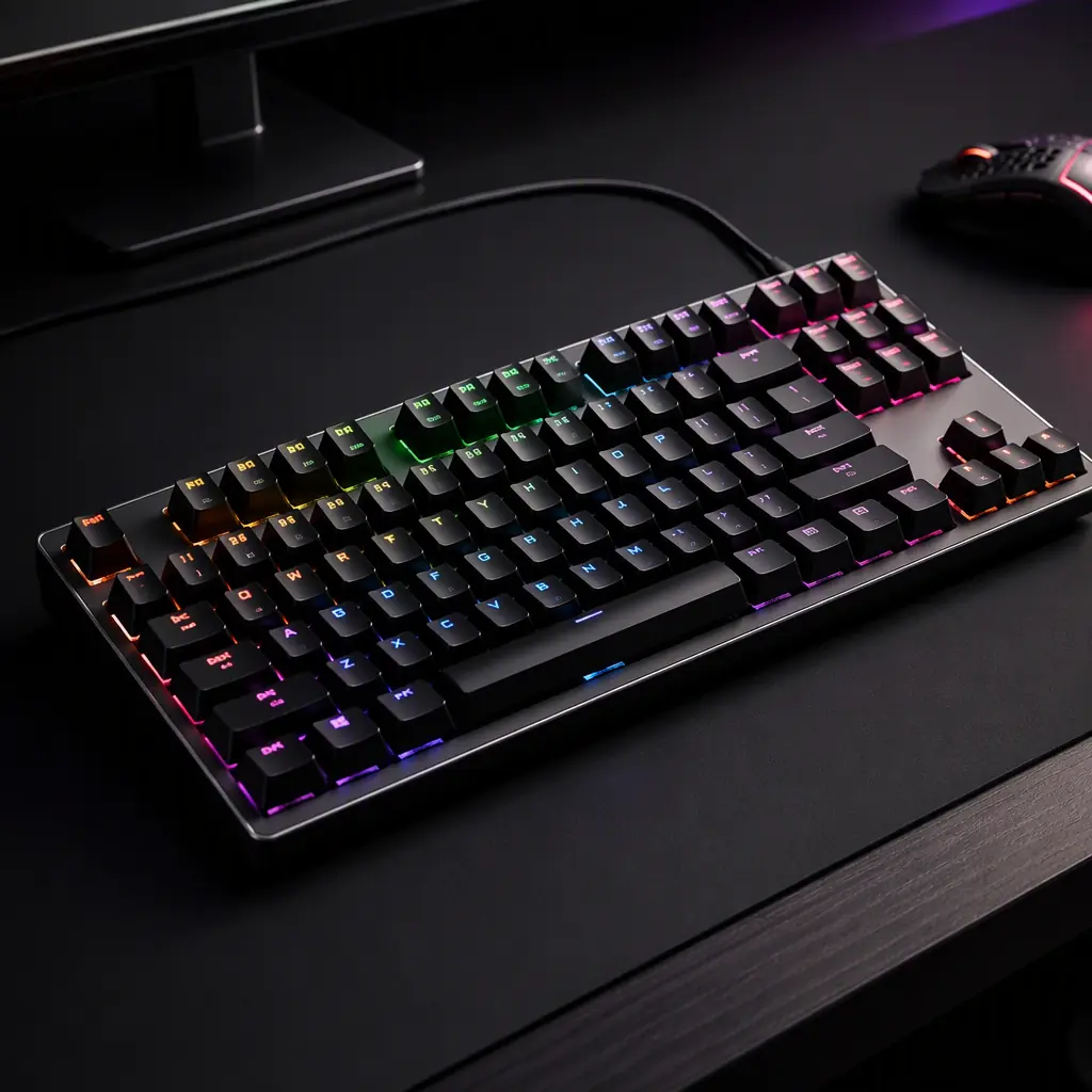
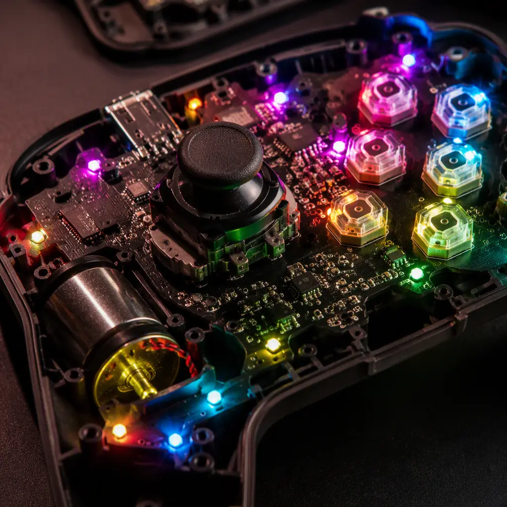
In esports, milliseconds and polling input are the difference between a registered input and a miss. A competitive gaming peripheral is engineered so the device adds as little latency and as much precision as possible. And almost all of that engineering lives on the board. A keyboard is a matrix of switches and LEDs scanned at high speed. A mouse is an optical sensor, a motion algorithm and a wireless radio. A controller is a bundle of sensors, haptics and radios. They are different products, but they share a common set of PCB problems.
What separates a competitive-grade board from a commodity consumer board is discipline: the polling rate is actually hit, the switch read is debounced correctly, the RGB light is even and flicker-free, and the wireless link stays low-latency without drawing the battery down. At Huaxing PCBA we build high-density consumer and peripheral boards with 8 SMT lines and 0201 / 0.3 mm pitch capability, holding a 98.7% first-pass yield across 150+ active customers.
The Polling Rate and the USB Report Budget
Polling rate is how often the peripheral sends a report to the host. A standard mouse reports at 125 Hz . Every 8 ms. A competitive mouse reports at 1000 Hz or higher: every 1 ms. The jump matters because, at 125 Hz, up to 7 ms of input latency is baked in before the PC even sees the input. At 1000 Hz the device is no longer the bottleneck.
| Polling rate | Report interval | Added latency | Typical use |
|---|---|---|---|
| 125 Hz | 8 ms | Up to ~7 ms | Office, casual |
| 500 Hz | 2 ms | Up to ~2 ms | Mid-range |
| 1000 Hz | 1 ms | Low | Competitive |
| 2000–8000 Hz | 0.5–0.125 ms | Minimal | Top-tier esports |
Hitting a high polling rate reliably is a firmware and a hardware question. The MCU has to be fast enough and the USB interface has to sustain the report rate without jitter. But it is also a power and layout question: a 1000 Hz mouse reads its sensor and radio more often, which draws more current and generates more noise. The board has to supply a clean rail at that higher duty cycle. Our power integrity design guide covers the decoupling that keeps a high-rate device stable.
Optical vs Mechanical Switches: Response and Debounce
Mechanical switches physically close a contact, which bounces, the voltage wavers for a few milliseconds before settling. That bounce has to be debounced, and debouncing adds latency. Optical switches interrupt a light beam instead, so there is no physical contact and no bounce, giving a faster and more repeatable switch event.
Debounce strategy and latency
For a mechanical switch, the firmware has to wait for the bounce to settle before registering the key. A longer debounce is more reliable but slower. The design has to balance the two. An optical or hall-effect switch removes most of the trade-off because it has a clean, single transition.
Key matrix scanning
A keyboard reads a matrix of rows and columns. Faster scanning means lower latency but more power and more switching noise. A well-designed matrix with diode isolation and a fast, deterministic scan is the foundation of a responsive keyboard. Diode direction and anti-ghosting are board-level decisions.
Switches and hot-swap sockets
Many competitive keyboards let the player swap the switch. Hot-swap sockets add convenience but also add a contact point and a little capacitance. The layout has to allow for socket contact and the durability expected by players, see our SMT vs through-hole and assembly process guides for the trade-offs.
Key Takeaway: Latency is won where the switch meets the firmware. Optical or hall-effect switches with minimal debounce hitting a fast, deterministic scan are what make a keyboard feel instant. Mechanical bounce is the enemy of a competitive input.
RGB LED Matrix: Driving Dozens of Lights Cleanly
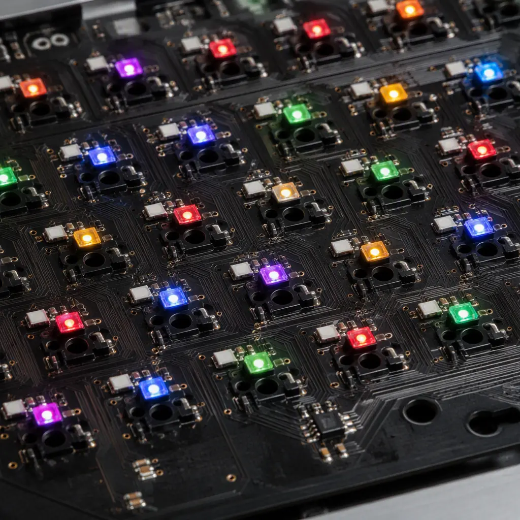
A competitive keyboard or mouse is defined visually by its RGB illumination. That means dozens of addressable LEDs, each capable of the full spectrum, driven at a fast update rate. The challenge is power: a bright keyboard backlight can draw a considerable current, and every LED has to be driven with a stable supply or the colors shift and flicker.
Parallel vs daisy-chain LED drive
Addressable LEDs (like WS2812-type) are typically daisy-chained, which simplifies routing but makes the data timing sensitive to capacitance and to the data rate. A higher-quality design may drive LED banks in parallel or with dedicated PWM channels for smoother, faster effects. The trade-off is BOM and complexity.
Power and current budgeting
Full-brightness RGB across an entire keyboard can draw several amps, which the 5 V USB rail may not deliver reliably. The board has to budget the current, and a quality design limits per-key brightness or uses a separate regulated rail so the LEDs do not cause the logic rail to sag. Sag produces visible flicker and can crash the MCU.
Low-voltage control of a high-current load
Driving power LEDs from a small MCU requires proper current control and thermal management. Our LED PCB manufacturing and thermal management guides cover the copper, via and thermal planning needed to keep an illuminated device cool.
Wireless and USB-C: Hybrid Connectivity, Low Latency, Real Battery Life
Modern gaming peripherals are hybrid, they work over USB-C for low latency and charging, and over a 2.4 GHz wireless link for freedom. The wireless link is the hard part: it has to be low-latency enough for competition and efficient enough for real battery life, while sharing a crowded 2.4 GHz band with a thousand other devices.
Antenna and RF layout
The 2.4 GHz antenna has to be tuned and the RF section has to sit on a well-controlled impedance and clean ground. A poorly-placed antenna or a noisy ground plane kills the link range and adds latency. Our PCB antenna design and RF PCB design guides are the reference here.
Battery and charging
A wireless mouse is powered by a lithium cell, charged over USB-C. The charging circuit has to be safe, efficient and not interfere with the radio. USB-C adds a PD and a cable-orientation dimension. Our USB-C PCB design and wireless power guides cover the interface and charging basics.
Power management for battery life
Battery life is a power-management problem. The MCU, sensor and radio have to sleep between events and wake quickly, and the board has to draw negligible power when idle. A device that reports a claimed 80-hour battery life but sips power in standby is a design with real low-power engineering behind it, see our low-power and energy harvesting guide.

The common thread across all of it is that a competitive peripheral is a real mixed-signal, power-managed, RF product, not a commodity consumer board. That means the MCU design, signal integrity and cost all have to come together. For the cost side of a volume peripheral, our PCB cost factors and BOM cost reduction guides are the reference.
What to Specify With a Peripheral Board Supplier
If you are bringing a gaming peripheral to market, the board is a large part of the product experience, and the supplier matters. The items below are the practical things to nail down. Because they are the ones that determine whether the product feels competitive or just looks the part.
| Specification | What to demand | Why it matters to the player |
|---|---|---|
| Polling rate | 1000 Hz minimum, verifiable on a scope | Lower input latency |
| LED current budget | Full-brightness with headroom, separate regulated rail | No flicker, consistent color |
| Switch response | Optical/hall option, minimal debounce | Faster, more repeatable actuation |
| Wireless range & latency | Tested link, tuned antenna | No dropouts in a crowded band |
| Battery life | Real measured, low standby current | Claimed spec actually holds |
Procurement Tip: Ask the supplier to demonstrate the actual polling rate and the full-brightness LED current draw, not just quote the ICs on the datasheet. A peripheral board that hits its spec is a design achievement; one that only looks like it does is a sampling problem waiting to surface at launch.
At Huaxing PCBA we build high-density consumer and gaming peripherals with 8 SMT lines, 4 DIP lines, 32-layer fabrication and 0201 / 0.3 mm pitch placement, in a 15,000 m² facility with 500+ staff serving 30+ countries. We are ISO 9001, IATF 16949 and UL (E354321) certified, with a 99.2% on-time delivery and 98.7% first-pass yield. Upload your design for a quote or talk to our engineering team about your gaming peripheral. For related applications, see our consumer electronics and smart speaker guides.
