

A collaborative robot shares a workspace with people, which changes everything about its electronics. An industrial robot only has to move precisely; a cobot has to move precisely and prove, with redundant, safety-rated electronics, that it will stop within milliseconds if a person enters its path or touches its arm. That requirement cascades down to the PCB level: dual-channel safety circuits, torque sensing on every joint, isolated motor drives, and control boards designed to a functional-safety standard rather than a cost target.
This guide covers the board-level architecture of a modern cobot, the safety controller, joint servo drives, torque and force sensing, power distribution, and the design rules that let a 6-axis arm claim ISO/TS 15066 compliance. Huaxing PCBA builds control boards, servo drive boards and sensor PCBs for collaborative and mobile robotics, and this is the engineering guidance our team applies to every robotics order.

The Cobot Electronics Stack: What Boards a Cobot Actually Contains
A 6-axis collaborative arm typically contains four families of PCBs, each with different requirements:
| Board Family | Function | Key PCB Requirement |
|---|---|---|
| Main control board | Motion planning, trajectory, I/O, networking | High-speed processor, DDR, high-layer-count |
| Safety controller (separate) | Independent stop logic, torque limits, E-stop path | Dual-channel, certified components, isolation |
| Joint servo drive | Motor commutation, current control, brake drive | High-current power stage, precise current sensing |
| Sensor / interface boards | Torque sensors, encoders, teach pendant link | Low-noise analog front end, shielding |
The critical architectural rule: the safety controller must be functionally independent from the main control board. It cannot share the same processor, the same firmware image, or even the same power rail without redundancy. This is the foundation of the PL d / SIL 2 ratings that cobot vendors target, and it is a PCB partitioning decision made on day one of the design. The broader functional-safety framework, SIL levels, redundancy, supplier qualification, is covered in our IEC 61508 functional safety guide.
Safety-Rated Control: Dual Channels, Independent Paths
ISO 10218-1 and ISO/TS 15066 require safety functions, stop, speed limiting, force limiting, to be implemented with a defined performance level. In practice that means the safety controller monitors the robot through two independent channels and requires agreement between them.
Two channels, one decision
The safety board reads joint positions, torque and the E-stop chain through two independent measurement paths . For example two encoders per joint (one on the motor, one on the output), or one encoder plus a redundant analog torque path. The two channels must be physically separated on the PCB: separate copper zones, separate connectors, no shared traces. A single shared trace is a single point of failure that voids the safety case.
The independent stop path
Every joint has a brake, and the brake-release signal must come from the safety controller through a path that the main controller cannot override. On the PCB this means a dedicated, isolated section of the board with its own voltage regulator and its own firmware watchdog. The brake drive itself: typically 24 V, 0.3–0.5 A per brake with an inductive flyback clamp. Needs robust layout to survive years of release cycles.
Certification-grade layout discipline
Functional-safety audits inspect the PCB: creepage and clearance between the safety channel and the power channel, component derating, trace width for fault current, and test points for every safety signal. The clearance rules follow the same high-voltage isolation discipline described in our high-voltage PCB design guide, even though a cobot runs at 24–60 V. The standard is about preventing single faults from becoming dangerous faults.
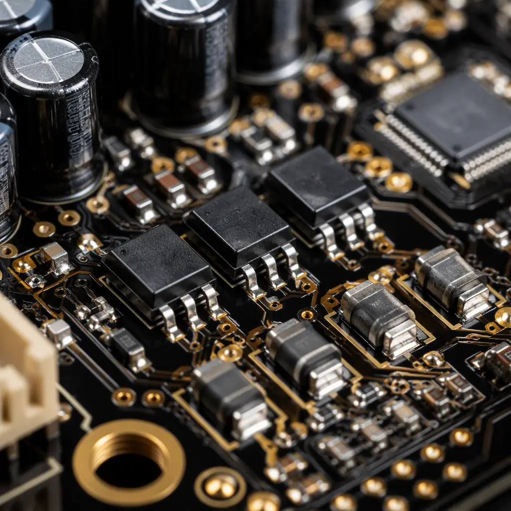
Key Takeaway: The safety controller is a separate board (or a fully isolated section) with dual-channel sensing, independent power and an un-overridable stop path. If the safety logic can be influenced by the main processor, the design does not meet PL d, no amount of testing fixes that.
Torque and Force Sensing: The PCB That Feels a Human Touch
The defining cobot feature is force limiting: the arm stops or reverses when it meets unexpected resistance. Force detection happens at three levels, each with its own electronics.
Joint torque sensing via current and strain
Every joint estimates torque from motor current, a cheap, fast proxy. For better accuracy, cobots add a strain-gauge or magnetoelastic torque sensor on the joint output. The strain-gauge analog path is a classic precision PCB problem: a mV-level bridge signal, a differential amplifier with gain of several hundred, and strict separation from the PWM motor drive below. The layout rules, guard rings, star grounding, dedicated analog ground zone, are the same as those in our mixed-signal PCB design guide.
Collision detection in the control loop
Beyond static torque limits, the controller compares expected torque (from the motion model) with measured torque every control cycle: typically 1 kHz. A deviation above threshold within one or two cycles triggers a stop. This works only if the current-sense path on the servo drive is accurate and noise-free; a noisy sense signal means either false stops (unusable robot) or a raised threshold (unsafe robot).
External force-torque sensors
Many cobots support a 6-axis force-torque sensor at the wrist for assembly and polishing tasks. These communicate over EtherCAT or CAN and draw their own power; the interface board must provide clean isolated power and a robust connector, because the wrist is the most mechanically stressed location on the arm. The high-speed data handling on these interface boards follows our high-speed connector PCB design guide.
Joint Servo Drive Design: Power Stage and Current Sensing
Each joint contains a servo drive PCB: a 3-phase inverter (typically 24–60 V bus, 5–20 A peak), gate drivers, a precision current sensor per phase, and the encoder interface. The drive is where power electronics and precision analog meet on one board.
| Drive Element | Typical Spec | Layout Priority |
|---|---|---|
| MOSFET bridge | 3-phase, 24–60 V, 5–20 A peak | Low-inductance loop, heavy copper |
| Current sensing | Shunt or hall, ±1% accuracy | Kelvin connections, sense trace routing |
| Gate drivers | Half-bridge, 100–600 ns | Short gate loop, bootstrap caps |
| Encoder interface | Absolute, 19–23 bit | Shielded traces, clean power |
The dominant layout rule is loop inductance: the MOSFET bridge, bus capacitors and current sense must form the smallest possible commutation loop, with 2 oz copper minimum on the power layer and a low-inductance capacitor right at the bridge. The gate drive loop must be equally tight. A long gate trace rings and can shoot through the bridge. The power-stage fundamentals are the same as those in our BLDC motor controller guide, and the thermal path, the drive sits inside a sealed joint, follows our thermal management guide.
DFM Tip: Specify the servo drive as a separate board from the safety controller even if space is tight. A combined board forces the power stage and the safety channel to share a substrate, which complicates the isolation audit and the thermal story. Two boards are cheaper to qualify than one that fails certification.
Power Distribution and EMC Across the Arm
The base supplies 24 V (or 48 V) to the whole arm over the cable harness. Each joint board needs its own local conversion, and the distribution must survive the noise environment of six PWM drives sharing the same harness.
Per-joint DC-DC with isolation
Each joint board converts the bus to its local rails (5 V logic, 3.3 V, ±15 V for analog), with the analog rail regulated after the digital switching to keep torque-sense noise down. Isolated converters separate the safety channel's power from the drive power, required for the redundancy argument.
EMC: the arm is one big antenna
A six-joint robot with PWM drives and long internal cables is an EMC nightmare. The PCB rules: input filtering at every board, common-mode chokes on the harness connectors, shielded encoder cables, and a single ground reference per board that ties back to the chassis. Compliance testing for CE/RED and the layout countermeasures are covered in our EMI/EMC design guide.
Inrush and hot-swap behavior
Powering the arm must not glitch the factory line: an inrush limiter on the base power board and per-joint soft-start keep the bus from sagging at power-on. This matters for fleets. A dozen arms powering up together can trip a branch breaker if none of them limit inrush.
Reliability and Testing for 24/7 Collaborative Operation
Cobots run double shifts, six or seven days a week, in environments from clean assembly lines to dusty machine shops. The reliability program is as important as the layout.
- Thermal cycling . Joints heat and cool with every work cycle; solder joint fatigue is the top field failure. IPC-9701 thermal cycling validation, as covered in our thermal cycling guide, is standard.
- Vibration and shock . The arm vibrates during motion; boards in the base and wrist need conformal coating and mechanical fixing beyond the connectors. Vibration-tolerant design is detailed in our AGV/AMR robot PCB guide.
- Burn-in . Every safety board ships after a burn-in cycle to catch infant mortality in the components that carry the safety case. The HASS/HALT methodology is covered in our burn-in and ESS testing guide.
Summary: The Cobot PCB Specification Checklist
When you spec PCBs for a collaborative robot, pin down eight things: a physically independent safety controller with dual-channel sensing; two encoders or redundant torque paths per joint; isolated power for the safety section; 2 oz copper and a tight commutation loop on every servo drive; a clean low-noise analog zone for torque sensing; input filtering and common-mode chokes on every harness connector; thermal cycling and burn-in in the test plan; and documentation of creepage/clearance for the PL d audit. A cobot is a safety system that happens to move. Its PCBs have to be engineered like the safety system they are.
Huaxing PCBA builds control boards, safety boards, servo drives and sensor PCBs for collaborative and mobile robots, with IPC Class 2/3, conformal coating and full traceability. Read our robotics PCB manufacturing guide for the broader robotics picture, or send our engineering team your robot's board stack for a free DFM and safety-layout review within 24 hours.
