
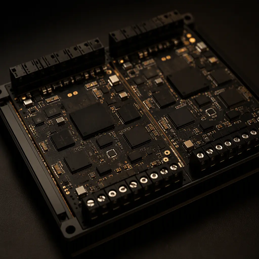
IEC 61508 is the generic functional safety standard that industrial, process, machinery and medical safety systems inherit from. When your product is a safety instrumented function, an emergency stop, a gas detector, a motor drive with safe torque off, a robot safety controller, the electronics must be designed, built and documented so that its probability of dangerous failure stays below a quantified target. For the PCB assembler in Shenzhen or anywhere else, that translates into a very specific set of demands: derated components, controlled processes, serialized traceability, verified test coverage and change control. Most of the work happens before the first board is built, in the specification and the supplier qualification.
This guide walks a procurement or quality manager through what IEC 61508 means for a PCBA purchase: how SIL levels map to failure-rate targets, which redundancy architectures change the bill of materials, what to write into the purchase order, and how to audit and qualify an assembly partner. If your product is automotive instead, the parallel standard is ISO 26262 with ASIL ratings, our ISO 26262 PCB assembly guide covers that branch in detail.
What IEC 61508 Actually Requires of the Hardware
IEC 61508 (Edition 2, 2010) organizes the safety lifecycle in seven parts. Part 2 is the one that matters most to a PCB buyer: it sets the requirements for the hardware, the random hardware failure target, the systematic capability, and the architectural constraints that apply to every safety function. Two concepts drive almost everything else:
Safety integrity level (SIL), the quantified target
SIL is a discrete grade from 1 to 4, each corresponding to a range of probability of failure. For low-demand safety functions (activated rarely, like a gas detector) the metric is PFDavg; for high-demand or continuous functions (like a drive's safe torque off) it is PFH. The higher the SIL, the tighter the range. And the more redundancy and diagnostics the hardware needs.
Safe failure fraction and diagnostic coverage
Not every failure is dangerous. The standard rewards designs that detect failures: diagnostic coverage (DC) is the fraction of dangerous failures the hardware detects before they matter. A SIL 3 loop typically needs DC of 90–99%. Which is why safety boards carry watchdogs, cross-monitoring, redundant ADCs and self-test routines, and why the PCB layout must support them (separate power islands, isolated test points, no shared return paths that mask a fault).
| SIL | PFDavg (low demand) | PFH (high demand, per hour) | Risk reduction factor | Typical DC needed |
|---|---|---|---|---|
| SIL 1 | 10⁻¹ – 10⁻² | 10⁻⁵ – 10⁻⁶ | 10 – 100 | 60–90% |
| SIL 2 | 10⁻² – 10⁻³ | 10⁻⁶ – 10⁻⁷ | 100 – 1,000 | 90–99% |
| SIL 3 | 10⁻³ – 10⁻⁴ | 10⁻⁷ – 10⁻⁸ | 1,000 – 10,000 | 90–99% (with redundancy) |
| SIL 4 | 10⁻⁴ – 10⁻⁵ | 10⁻⁸ – 10⁻⁹ | 10,000 – 100,000 | ≥ 99% (rare outside rail/aviation) |
Key Takeaway: A "SIL 3 certified board" is a claim about the whole safety function, not the PCB alone. What a buyer can and should demand from the assembler is: the BOM and process were built to the design's FMEDA assumptions, and the manufacturing evidence (traceability, test results, change records) survives an audit. Everything else lives in the design house's safety case.
Redundancy Architectures: 1oo1, 1oo2 and 2oo3 on Real Boards
To reach SIL 2 and above, the architecture must tolerate a dangerous failure of one channel without losing the safety function. The voting scheme is written into the system design, but it reshapes the PCB: more channels, isolation between them, and stricter layout rules so that a single physical fault cannot take down both paths (that would be a common-cause failure, and the FMEDA counts it as one dangerous point).
1oo1, single channel with diagnostics
One channel executes the safety function; diagnostic coverage catches failures and forces the safe state. Used at SIL 1 and sometimes SIL 2. On the board: one processor domain, one watchdog, self-test coverage in firmware. The layout must give the diagnostic paths (voltage monitors, current sensors) clean, independent references.
1oo2, two channels, either can act
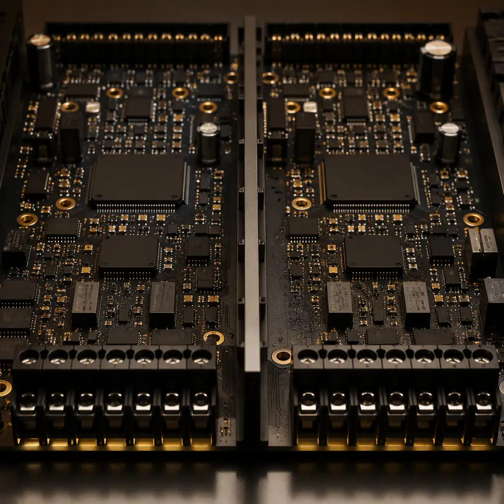
Two independent channels both execute the function; if one fails dangerously, the other still acts. This is the classic SIL 3 architecture for safety PLCs and drives. The PCB must keep the channels electrically independent: separate power feeds, separate crystal domains, physical spacing between the two processor areas, and no shared bus that a single solder bridge could short. Cross-channel comparison logic needs its own partition.
2oo3, majority voting for availability
Three channels, any two must agree. Used where a spurious trip is as costly as a missed trip (process plants, rail signaling). The PCB carries three channel areas plus voting logic. A board that is physically larger, with more stringent spacing so a single contamination or arc cannot corrupt two channels. The supplier quality scorecard approach helps you weigh which assemblers can hold these processes consistently.
Component Selection for Safety-Critical Boards
The FMEDA (Failure Modes, Effects and Diagnostic Analysis) in the safety case assigns a failure rate to every component. The assembler's component choices can silently invalidate those numbers. Which is why safety buyers control the BOM so tightly.
Derating is a design input, not a suggestion
Most safety projects derate passives and semiconductors to 50–70% of rated voltage/power to keep junction temperatures low, a 70 °C junction instead of 105 °C changes failure rates by an order of magnitude. The purchase order should state the derating rules and the ambient profile (e.g., 85 °C continuous), and the assembler's solder profile and rework policy must not push parts outside their derated envelope.
Industrial-temperature and long-life parts only
Specify -40 to +85 °C (or +105 °C) rated components, AEC-Q or industrial grades for actives, and low-ESR, high-reliability passives. Consumer-grade parts that drop out of specification above 70 °C are a common root cause of field returns in safety equipment. Component selection also intersects with counterfeit risk, see our counterfeit detection guide for the authentication steps to write into incoming inspection.
Plan obsolescence before the first build
Safety-certified products have 15–25 year lifetimes and a recertification cost every time the BOM changes. Every alternate part in the FMEDA must be pre-qualified. An alternate that is electrically identical but has a different failure mode profile can invalidate the SIL claim. Require the assembler to flag any component change through a formal change request, not a substitution note. Our obsolescence management guide covers the EOL planning mechanics.
What to Write Into the Purchase Order
A safety PCBA order is a contract for evidence, not just boards. These clauses turn "functional safety" from a marketing word into an auditable requirement:
Traceability to serial or lot level (IPC-1782)
Demand lot-level (and for SIL 3, board-level) traceability: which solder paste lot, which stencil, which reflow oven profile run, which AOI and x-ray results, which operator. IPC-1782 defines the traceability classes. Specifying Class 3 for safety boards is now standard practice. Our IPC-1782 traceability guide lists the data records to collect.
100% test coverage with kept records
Safety boards are typically 100% electrically tested, ICT plus boundary scan plus functional test, with the test data archived per serial number. The purchase order should name the test methods and require that failed boards are quarantined with the failure data (including x-ray and cross-section when needed) retained for the product lifetime. Our test method comparison helps you choose the right combination.
Conformal coating and environmental protection
Industrial safety electronics operate in dust, humidity and condensation. Specify conformal coating type and thickness (acrylic, silicone or parylene), and require coating inspection coverage, see our conformal coating guide for the IPC-A-610 coating acceptance criteria and the masking requirements for test points and connectors.
Burn-in or environmental screening where the FMEDA expects it
For SIL 2+ hardware, the safety case often assumes burn-in or temperature cycling to catch infant mortality before the product ships. If the design calls for it, the PO must specify the burn-in profile (temperature, duration, monitored parameters) and the acceptance criteria. Our burn-in and ESS guide covers HASS and HALT options.
Supplier Qualification: The Audit Checklist
IEC 61508 does not certify assembly factories, certification applies to products and their safety cases. What a factory must demonstrate is the process capability to build per the design's assumptions, repeatedly, with evidence. Qualify the supplier on these points before the first production order:
Quality system and change control
ISO 9001 is the baseline; for medical-adjacent safety products ISO 13485 helps. The critical audit point is change control: how the factory handles component, process and equipment changes, and whether it will issue a formal notification before substituting anything on a safety BOM. A factory that routinely swaps components to chase price is disqualified regardless of its certificates.
Test infrastructure and failure analysis depth
Can the factory actually run the test coverage your design requires, boundary scan, functional test fixtures, x-ray, cross-section, thermal cycling? Does it have failure analysis capability (micro-section, SEM, dye-and-pry) to investigate a field return and close the loop with an 8D report? The failure analysis guide describes the investigation ladder a serious supplier should have.
Quality metrics and field data
Ask for DPPM, first-pass yield and field return data over the last 12 months, segmented by customer or product line if available. A supplier that cannot produce its own quality numbers cannot support your safety case's assumptions about manufacturing quality. Our DPPM benchmarks guide tells you what numbers are realistic for a mid-size EMS in China.
Audit evidence, not promises
Run a structured supplier audit covering the five M's, man, machine, material, method, measurement, with specific attention to ESD control (ANSI/ESD S20.20), moisture handling (IPC/JEDEC J-STD-033) and solder paste storage. For remote qualification, a live video walkthrough of the SMT line and test area plus sample records is a workable alternative; our remote audit guide has the protocol.
Sourcing Safety-Critical PCBA: The Buyer's Bottom Line
Functional safety is a chain: the safety case defines the targets, the design implements them, and manufacturing either preserves or silently destroys them. As the buyer, your leverage is the purchase order, specify the SIL target and its metrics, the redundancy and isolation expectations, the derating and temperature grades, the traceability class, the test coverage, and the change-control obligations. Then qualify the supplier against those clauses with an audit, and verify the evidence on the first article and every lot after.
At Huaxing PCBA we assemble safety-critical industrial boards with 100% electrical test, serialized IPC-1782 traceability, conformal coating and burn-in capability across 8 SMT lines, under ISO 9001 with IATF 16949 process discipline. Read our PPAP guide for the documentation package, or send your BOM and safety specification . We will confirm we can hold your traceability and test requirements before quoting.
