

The difference between an AGV (Automated Guided Vehicle) and an AMR (Autonomous Mobile Robot) is navigation: AGVs follow fixed magnetic tape or wire paths, while AMRs build a map with SLAM and plan their own routes around obstacles. That difference is mostly software, but it drives a hardware gap in compute power, sensor count, and PCB design complexity. An AMR typically carries a 6–8 layer main board with a quad-core application processor, a separate MCU for motor control, and a safety-rated stop circuit that must work independently of the main compute.
This guide covers the electronics architecture and PCB layout rules for AMR-class robots: the navigation compute module, the sensor fusion interfaces (LiDAR, cameras, IMU, encoders), the motor controller's power stage, the battery and wireless charging system, and the safety circuits that industrial buyers will audit before they put your robot on their factory floor. We build these boards at Huaxing PCBA. Our 8 SMT lines handle the 0201 passives and 0.3 mm-pitch BGAs these dense designs require, and our X-ray and ICT coverage catches the defects that vibration will expose later. For the motor-drive fundamentals, pair this with our BLDC motor controller PCB guide.
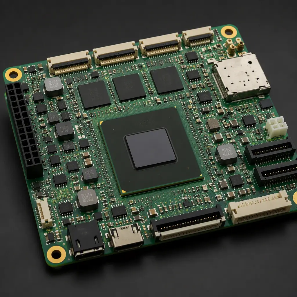
System Architecture: Splitting Compute from Motion Control
The first architectural decision is whether navigation and motion control share one processor. For a safety-related reason they should not: the motor controller must keep executing (or safely stopping) even if the navigation OS crashes. A watchdog cannot stop a robot moving at 2 m/s before it hits a person. The motor drive needs its own MCU with an independent safety path.
Two-board vs single-board architecture
Entry AGVs use one board (application processor + motor MCU on the same PCB) to save cost. AMRs above 200 kg payload or with safety certification split into a compute board (quad-core SoC, RAM, eMMC, Wi-Fi) and a motion board (motor drivers, encoders, E-stop, relays). The split isolates the noisy power stage from the sensitive navigation electronics, the same logic as our mixed-signal partitioning guide, at system level.
Communication between boards: CAN bus is the default
CAN is the standard backbone for AMR internals, the compute board publishes trajectory commands, the motion board publishes encoder and current feedback, and the battery BMS publishes state of charge. Use a shielded twisted pair, 120 Ω termination at both ends, and our CAN transceiver layout rules. If your robot has remote I/O modules (sensors, lights, grippers), CAN or EtherCAT keeps the wiring harness simple.
Compute board essentials: power sequencing and decoupling
An AMR compute board is a small server: SoC, LPDDR4, eMMC, Wi-Fi/BLE module, and USB cameras. Follow the SoC reference design for power sequencing (always-on rail → core → I/O), place the PMIC close to the SoC, and budget at least 10 µF of local decoupling per power rail. Our MCU PCB design guide covers the sequencing and decoupling patterns.
Key Takeaway: Separate the safety-critical motion control from the application processor. It is the single most important architectural rule in AMR design, and the one most cost-driven prototypes skip, only to re-spin at certification time.
Sensor Fusion Layout: LiDAR, Cameras, IMU, and Encoders
An AMR navigates by fusing LiDAR point clouds, camera images, IMU data, wheel encoders, and sometimes UWB or QR-code landmarks. Each sensor has an interface that must be routed correctly or the fusion stack silently degrades. The robot drifts, misjudges obstacles, and no one can debug why because the software logs look fine.
LiDAR interface: Ethernet or UART, never shared with motor noise
Most AMR LiDAR units output point clouds over 100 Mbps Ethernet or high-speed UART. Route these as differential pairs with the transceivers near the connector, and keep the LiDAR cable path away from the motor phase wires. A 20 A motor phase switching at 20 kHz will couple into an unshielded sensor link. Add common-mode chokes on the Ethernet magnetics and TVS diodes on every external connector. For high-speed interconnect rules, see our Ethernet PHY layout guide.
Camera interface: MIPI-CSI routing discipline
Navigation cameras use MIPI-CSI-2 lanes at 800 Mbps–1.5 Gbps per lane. Route differential pairs length-matched to ±5 mil, keep 3× the dielectric height away from other signals, and place the connector so the flex cable does not fold over the SoC's decoupling caps. Our camera module PCB guide has the full MIPI routing checklist.
IMU placement: mechanical isolation beats filtering
The IMU must sit near the robot's center of rotation: usually directly under the navigation board's mounting screws, because vibration and thermal asymmetry corrupt its readings. Route the IMU's I2C/SPI with series resistors and keep the trace short; the motor vibration problem is solved mechanically (soft mounts, damped chassis) not in firmware. Encoder inputs (quadrature) need Schmitt-trigger buffers or opto-isolation if the encoder cable runs alongside motor wires.
Motor Controller PCB: The Power Stage That Must Not Fail
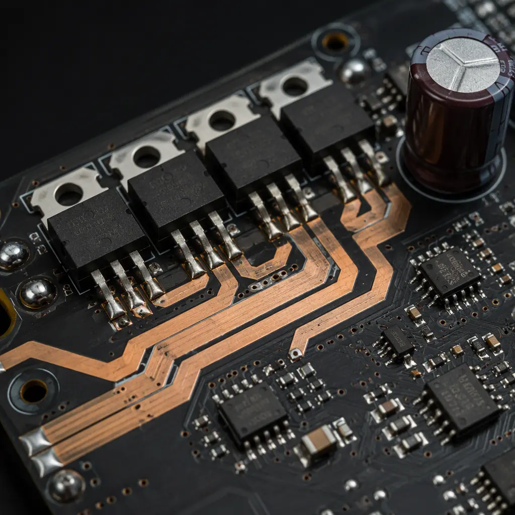
The motion board's motor driver is the highest-stress PCB in the robot. For a 300 kg AMR with 4 drive wheels, each motor draws 10–30 A continuous with 50 A peaks. And a MOSFET failure while carrying a load is both a safety and a cost event. The layout rules are the same ones used in EV traction inverters, scaled down. Our BLDC controller guide and traction inverter guide cover the physics; here are the AMR-specific decisions.
| Parameter | Entry AGV | Mid AMR (100-300 kg) | Heavy AMR (500+ kg) |
|---|---|---|---|
| Drive wheels | 2 (differential) | 2-4 | 4-6 |
| Motor power per wheel | 200-400 W | 500 W-1 kW | 1.5-3 kW |
| Battery voltage | 24 V | 24-48 V | 48-72 V |
| Phase current (peak) | 15 A | 30-50 A | 80-120 A |
| MOSFET package | DFN 5×6 | TO-263 / DFN 8×8 | TO-247 modules |
| Gate driver isolation | None (low-side) | Optional | Required |
Copper budget and thermal vias for 30 A phases
For 30 A continuous phase current, use 2 oz (70 µm) copper on the power layers and at least 4–6 thermal vias (0.3 mm) under each MOSFET pad down to a dedicated heatsink plane. The phase traces must be wide enough for < 10 °C temperature rise. That is roughly 6-8 mm of 2 oz copper per 30 A. If the board is thicker than 1.6 mm, the thermal vias must be filled or the heat cannot reach the bottom plane. Our trace width calculator guide gives the exact figures.
Gate drive layout: the loop that determines switching speed
The gate driver to MOSFET gate loop must be as small as possible, gate resistor, gate-source cap, and driver output within a 5 mm radius. A large loop adds inductance that causes gate ringing, EMI, and MOSFET shoot-through at high dV/dt. Use Kelvin-source connections for the current-sense path so the sense resistor's voltage drop is not polluted by the power loop.
Bulk capacitance and the battery connection
The battery is meters of cable away from the board, the cable inductance rings with the MOSFET switching. Place 2-4 aluminum polymer or ceramic bulk caps (470 µF class) right at the battery input connector, plus a 0.1 µF ceramic across each half-bridge. If the motor can regenerate (braking), the bulk caps must absorb the energy; size them for the worst-case deceleration event.
Power and Battery: 24-48 V Systems with Wireless Charging
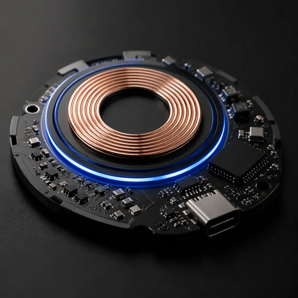
AMRs are typically charged by contact pads or wireless (inductive) charging stations. The battery system is a multi-cell Li-ion pack with a BMS, and the charging path must handle both the pack's charge profile and the robot's inrush when it connects to the station.
BMS and cell monitoring on the motion board
For 24 V (7S) to 72 V (20S) packs, use a dedicated BMS board or IC with cell-balancing, over/under-voltage, and over-temperature protection. The cell-sense wires are long and noisy, filter each with an RC network at the BMS input and route them away from the phase wires. See our EV BMS PCB design guide for the isolation and sensing patterns.
Contact charging: pre-charge circuit to stop sparking
Contact chargers spark when the robot docks at 48 V. Add a pre-charge path (series resistor + MOSFET) that charges the bulk caps through a limited current for 100-300 ms before the main contactor closes. This is mandatory for any voltage above 24 V, the spark erodes the contact pads and creates EMI that resets the navigation stack. Wireless charging avoids the contact problem entirely; our wireless charging PCB guide covers the coil and rectifier layout.
Safety Circuits: E-Stop and the Independent Stop Path
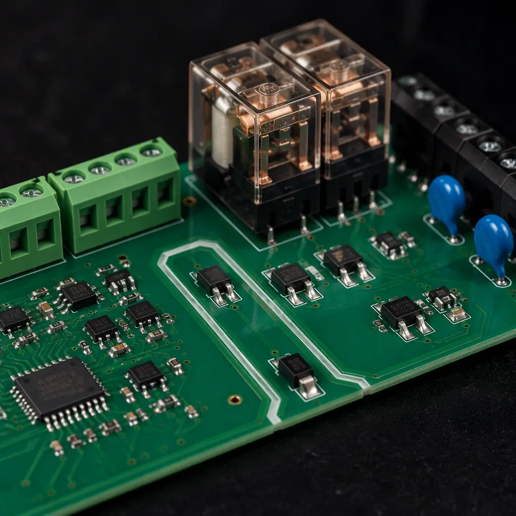
Industrial buyers will ask one question before any other: what happens when the E-stop is pressed? The answer must be a hardware path that removes motor power independently of the software. This is where AMR certification (ISO 3691-4, ISO 10218) and the electronics design intersect.
Dual-channel E-stop with a dedicated safety MCU
The E-stop circuit should be dual-channel (two independent switches or contacts) feeding a safety-rated MCU or a hardwired relay chain that cuts the motor supply. The safety path must not share the main MCU, the same PCB power plane, or the same firmware. Route the E-stop wires with 2 mm creepage from other circuits and add a TVS on the connector.
Brake control: fail-safe = brake engaged when power is removed
Drive motors on inclined surfaces need holding brakes that engage when power is removed. The brake driver must be an independent output on the motion MCU (or the safety chain), never driven only by the application processor. A spring-applied, electrically-released brake is the fail-safe standard for AMRs over 100 kg.
Procurement Tip: Before signing with a CM for AMR boards, verify three things: X-ray capability for the 0.3 mm-pitch BGA compute modules, conformal coating lines (robots run in dusty warehouses), and vibration/burn-in testing. Our vibration testing guide explains the JESD22-B103 profiles an AMR board must survive.
Reliability and Testing for 24/7 Robot Operation
A warehouse robot runs 16–20 hours a day, seven days a week. The electronics must survive thermal cycling from cold dock to loaded climb, vibration from rough floors, and ESD from the charging contacts, for a service life of 3–5 years.
Conformal coating and connector strain relief
Specify acrylic or silicone conformal coating (0.05–0.1 mm) on the compute and motion boards, masked off at connectors and test points. All cable connectors need strain relief. A robot that vibrates a JST connector loose mid-shift is a safety incident. Our conformal coating guide covers material selection.
Burn-in and functional test before shipping
Require 4–8 hours of powered burn-in with a test program cycling the motors, sensors, and communication interfaces, plus a functional test that simulates a full duty cycle. The cost of catching an intermittent solder joint in burn-in is a hundred times less than a field failure on a customer's floor. See our burn-in and ESS guide for the test design.
Building AMR Boards at Scale
AMR production is a balancing act: prototype volumes of 10–50 boards need fast turns and DFM flexibility, while production volumes of 1,000–10,000 boards need process control, traceability, and burn-in capacity. The best CMs for robotics are those that do both. And that can show you their X-ray and burn-in lines, not just their SMT machines.
At Huaxing PCBA, we assemble AMR and AGV control boards from 6 to 32 layers, with 0201 placement, 0.3 mm-pitch BGA X-ray inspection, conformal coating, and 24-48 hour quick-turn prototypes alongside volume production. Send us your design files for a DFM review. You will get assembly feedback on the power stage, connector placement, and test strategy within 24 hours. Contact our engineering team, or read our industrial control PCB guide for the wider factory-automation picture.
