
Controller Area Network is the wiring backbone of virtually every vehicle and most industrial machinery: a single modern car carries 30-70 CAN or CAN FD nodes, and a production line may daisy-chain dozens of control boards over a 40-meter bus. The protocol itself is famously robust — differential signaling, CRC checking, and error confinement recover from most bit errors automatically. When a network does fail in the field, the root cause is usually not the software stack but the physical layer: marginal termination, excessive stub length, or an EMI problem that corrupts recessive bits.
Huaxing PCBA builds CAN and CAN FD node boards for automotive, industrial, and e-mobility customers — IATF 16949 certified, 2-32 layers, 3/3 mil fine-line capability, and 8 SMT lines with X-ray and full functional test support. Our DFM engineers review every automotive layout for the bus-specific rules in this guide before tooling. This article covers transceiver placement, differential routing, termination strategies, common-mode filtering, isolation, and the manufacturing specifications that determine whether your bus passes EMC testing on the first attempt.
Why the Physical Layer Decides Network Reliability
CAN is a multi-master, broadcast bus where every node listens while it transmits and detects collisions through bit monitoring. That arbitration mechanism only works if every node sees the same dominant/recessive levels at the same time — which makes signal quality on the wire a protocol-level concern, not just an analog nicety. Two timing parameters put hard constraints on the layout.
Bit Time Budget: Propagation Delay Must Fit the Sample Point
At 500 kbit/s a CAN bit lasts 2 µs; the transceiver sampling point sits near 75-87.5% of the bit time. The round-trip propagation delay of the bus — cable, transceivers, and PCB traces — plus the oscillator tolerance must fit inside that window. A rule of thumb for 500 kbit/s is a maximum bus length around 40 m with 5 ns/m cable delay; at 1 Mbit/s that shrinks to roughly 25 m. CAN FD pushes data rates to 5-8 Mbit/s in the data phase, where propagation delay budgets become so tight that every centimeter of extra trace or every extra connector in the path is measurable.
Stub Length: The Un-Terminated Branch Is a Reflection Point
Every node connects to the bus through a stub — a short pair of traces from the transceiver to the main trunk. Classic CAN tolerates stubs up to about 0.3 m at 500 kbit/s (per ISO 11898-2), but at CAN FD data rates the recommended stub drops to 10 cm or less. The layout equivalent: keep the transceiver as close to the connector as physically possible, and treat long node traces as a transmission-line problem, not a wiring convenience.
Recessive Bits Are Easy to Corrupt — EMI Turns a 1 into a 0
CAN bus levels are 2 V or less between CANH and CANL in the dominant state, and the recessive state is a weakly driven, high-impedance state that any noise source can pull toward the threshold. Automotive transients (ISO 7637-2 pulses, load dumps up to 40 V) and radiated noise from adjacent high-current switching (motor drivers, DC-DC converters) are the classic corruptors. This is why transceiver choice, common-mode chokes, and TVS protection are not optional extras — they are part of the signal-integrity design.
Key Takeaway: CAN works because every node agrees on bit timing and sees clean differential levels. Your PCB layout — stub length, termination, and filtering — directly sets how much timing and noise margin the network has left.
Transceiver Placement and Power Decoupling
The transceiver is the interface between the protocol controller (often an MCU with an integrated CAN controller) and the physical bus. Common parts include the NXP TJA1044/TJA1051, TI TCAN1042, and Infineon TLE9250 families; CAN FD-capable transceivers add faster slew-rate control and often a standby mode with a dedicated wake-up pin. Our automotive PCB requirements guide covers the overall board context; here are the CAN-specific placement rules.
Place the Transceiver at the Board Edge, Next to the Connector
The trace from the connector to the transceiver is part of the bus stub, so it must be as short as possible — target under 25 mm for CAN FD. Put the transceiver on the same side of the board as the connector, with the CANH/CANL pins facing it. Avoid routing the differential pair through vias on the way in; if a via pair is unavoidable, place them symmetrically and close together to keep the pair balanced.
Decouple VCC at the Transceiver, Not Just at the MCU
A 100 nF ceramic capacitor within 3 mm of the transceiver VCC pin, plus a 10 µF bulk capacitor nearby, handles the current spikes during dominant-bit transitions. Place the capacitor on the same layer as the IC if possible, with a direct via to the ground plane. Weak decoupling shows up as bit errors exactly at high temperature or high data rates — the two conditions that are hardest to debug in the field.
Route TXD/RXD Away From the Bus Pins
The microcontroller-side signals (TXD, RXD, and the CAN controller clock) are single-ended and noisy; the bus-side signals (CANH, CANL) are differential and sensitive. Keep a ground trace or plane gap between the two domains, and never run TXD parallel to CANH/CANL for more than a few millimeters. Digital noise coupled into the bus pins raises the error rate at exactly the wrong time — during arbitration.
Differential Pair Routing: 120 Ohm, Tightly Coupled, Over a Solid Plane
The CAN physical layer is specified for a characteristic impedance of 120 Ω on the cable, and the PCB portion of the network should match that as closely as practical. Unlike USB or Ethernet, CAN does not require an impedance-controlled PCB for short stubs — but modern high-speed CAN FD designs and long board-to-board links benefit from controlled differential impedance.
Use 120 Ω Differential Impedance With Tight Intra-Pair Spacing
On a typical 1.6 mm FR-4 stackup, a 120 Ω differential pair can be built with 0.2 mm (8 mil) traces and 0.2 mm spacing on an outer layer, or wider traces on inner layers. Keep the pair edge-coupled (side-by-side) rather than broadside, and maintain the same spacing for the entire route — the impedance of a CAN pair is set by geometry, and any abrupt width or spacing change creates a reflection. Huaxing supports impedance control to ±5% with coupon testing on every panel.
Length-Match CANH and CANL Within a Few Millimeters
Skew between the two legs of the differential signal eats into the receiver's common-mode rejection. Keep CANH and CANL length-matched within 5 mm for classic CAN, tighter for CAN FD. Because both traces are short and parallel, this is usually automatic — the risk appears when one leg is routed around an obstacle while the other goes straight.
Solid Ground Reference, No Splits Under the Pair
Route the pair over a continuous ground plane on the adjacent layer. A split in the plane under the traces — for example, a moat used to isolate an analog section — forces return current to detour and converts a clean differential signal into a loop antenna. If the board has multiple ground domains, keep the entire CAN physical layer in one domain or bridge the split with the common-mode choke (see below).
| Parameter | Classic CAN (ISO 11898-2) | CAN FD Data Phase |
|---|---|---|
| Max data rate | 1 Mbit/s | 5-8 Mbit/s |
| Bus impedance | 120 Ω | 120 Ω |
| Max stub length | 0.3 m (typ.) | 0.1 m (typ.) |
| Differential output | 2 V (dominant) | 1.5-2 V (dominant) |
| Node count | Up to 32 (typ.) | Up to 32 (typ.) |
| Termination | 120 Ω at both ends | 120 Ω at both ends |
Termination: The Most Common Field Failure
A CAN bus must be terminated with 120 Ω at each physical end of the trunk — exactly two terminations, no more, no less. Missing termination causes reflections that show up as intermittent errors at high speeds; extra termination loads the transceivers and can prevent the recessive level from being reached at all. This is the single most common cause of "works on the bench, fails in the field" CAN complaints.
Two 120 Ω Resistors, One at Each End of the Trunk
Identify which two nodes are physically at the ends of the bus and place the termination there — typically the gateway and the last sensor node. Resistor tolerance matters: use ±1% resistors so the two terminations stay balanced. On boards that can be either a middle node or an end node (common in modular designs), fit the resistor through a solder jumper or 0 Ω link so the same board works in both positions.
Split Termination (60 Ω + 4.7 nF) When You Need Cleaner Emissions
A split termination replaces each 120 Ω resistor with two 60 Ω resistors and a 4.7 nF capacitor between the midpoints, creating a low-pass filter at the end of the bus that shaves high-frequency common-mode energy. This is a common EMC fix in automotive ECUs. The capacitor value trades emissions against signal quality — stay in the 4.7 nF range for classic CAN and check the transceiver datasheet for CAN FD, where the extra capacitance can slow edges.
Biasing: Weak Pull-Ups Keep the Recessive State Well-Defined
When all transceivers are in the recessive (high-impedance) state, the bus floats. A bias network — typically 10 kΩ pull-up on CANH and 10 kΩ pull-down on CANL at one designated node — pins the idle level near 2.5 V. Many transceivers include internal biasing (TJA1044 does; TJA1051 does not), so check the datasheet before adding external parts. Consistent idle level is what prevents spurious dominant bits when the network powers up.
Common-Mode Chokes, TVS and Transient Protection
Automotive and industrial buses are exposed to transients that no signal-integrity textbook assumes: load-dump pulses, inductive kickback from solenoids and motors, and ESD from connectors and harnesses. Three components handle most of it.
Common-Mode Choke: 51 µH or 100 µH, Placed Between Connector and Transceiver
A common-mode choke (CMC) passes the differential CAN signal while blocking common-mode noise that radiates from the harness — the main source of radiated-emission failures in CISPR 25 automotive tests. Typical values are 51 µH (TJA1044 reference designs) or 100 µH for harsher environments. Place the CMC between the connector and the transceiver, with its ground pin connected to the chassis/ground plane. The CMC is also the natural bridge point if the connector side of the board is a separate ground domain.
TVS Diodes: Bidirectional, Rated for the Bus Voltage
Place a bidirectional TVS diode (e.g., PESD1CAN family, or a 24 V bidirectional part for 24 V vehicle systems) directly at the connector pins, before the CMC. The diode clamps ESD and surge energy before it reaches the transceiver. For ISO 7637-2 pulse immunity, some designs add a series resistor or use transceivers with integrated protection (the TJA1044T/3 and TCAN1042V variants include built-in ±58 V bus fault protection).
Series Resistors on CANH/CANL for Extra Margin
A 10-30 Ω series resistor on each bus line, between the CMC and the transceiver, damps ringing and adds fault current limiting. Some automotive reference designs use these in combination with the CMC to tune edge rates. Do not confuse these with termination — they are in series, not across the pair, and both lines must carry the same value to keep the pair balanced.
Factory Reality: At Huaxing, every automotive CAN board is assembled with solder-paste inspection (SPI), AOI, and X-ray for BGA and shield components — then functionally tested on a live CAN bus with a configurable termination network, so a missing 120 Ω resistor is caught before shipment, not by your field team.
Isolation and Multi-Node Network Design
Industrial CAN networks frequently need galvanic isolation between nodes — a motor drive and a PLC on the same bus can sit at very different ground potentials, and a ground loop through the CAN cable is both an EMC disaster and a safety hazard. Our industrial control PCB guide covers the broader design context.
Use a Galvanically Isolated Transceiver for Industrial Nodes
Parts like the ISO1042 or ADM3053 integrate isolation (up to 5 kVrms) inside the transceiver package, eliminating a separate isolation barrier design. The isolated side needs its own DC-DC supply — often a small isolated module or a transformer-based design — and a dedicated isolated ground plane under the bus-side circuitry. Keep the isolation barrier (the gap under the IC) clear of traces on all layers.
Topology: One Linear Trunk, Short Stubs — Not a Star
CAN is specified for a linear bus with short stubs. Star topologies create multiple reflection points and require special care (termination at each spoke end, or a hub node with repeaters). If the mechanical layout forces a star, budget for a CAN repeater or a hub board rather than hoping the transceivers absorb the reflections.
Plan Node Count and Cable Length Against the Bit Rate
Classic CAN supports 32 nodes at 1 Mbit/s over a short bus; at 125 kbit/s the bus can stretch to 500 m. More nodes mean more stub capacitance and more loading, which slows edge rates. If your system needs more nodes than the transceiver family supports, use a second bus segment with a gateway instead of overloading one segment.
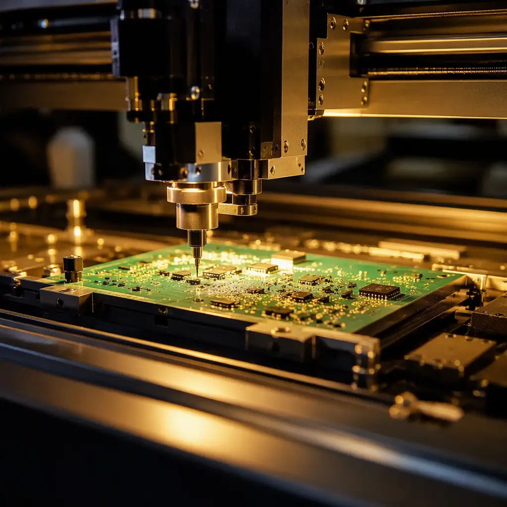
Manufacturing Specifications to Put on the Fabrication Drawing
The layout rules above only deliver their value if the board is manufactured to the right tolerances. When you send your CAN node board to a fabricator, specify the following explicitly — our manufacturing tolerances guide explains the standard values in detail.
Impedance Control on the CAN Pair (If Specified)
If you design for 120 Ω differential impedance, require impedance coupons on the panel and a TDR report. Huaxing tests impedance to ±5% and includes the report with the shipment.
Copper Weight and Trace Width for the Bus Pins
Bus pins carry only signaling current, but the connector pads and the power pins of the transceiver can carry real current in fault conditions. Standard 1 oz copper with 0.2 mm traces is adequate for the signal pair; widen the VCC and ground traces to the transceiver to 0.5 mm or more.
Conformal Coating for the Bus Side (Optional but Common)
Automotive and industrial boards often specify conformal coating on the connector-side circuitry to resist vibration, moisture, and salt. If you plan to coat, mask the test points and any calibration area — and note that coating over the termination resistors is fine as long as the values are final.
Summary: The CAN Node Board Checklist
A reliable CAN node board has the transceiver within 25 mm of the connector, a tightly coupled 120 Ω differential pair over a solid ground plane, exactly two 120 Ω terminations at the physical ends of the trunk (split or biased as the EMC plan requires), a common-mode choke and TVS between connector and transceiver, clean decoupling on the transceiver supply, and a layout that keeps single-ended digital signals away from the bus pins. On the production side, specify impedance coupons, AOI plus functional bus testing, and — for automotive — IATF 16949 process control from an audited supplier.
At Huaxing PCBA we manufacture CAN, CAN FD, and isolated industrial node boards up to 32 layers with controlled impedance to ±5%, 3/3 mil fine-line routing, and full assembly support across 8 SMT lines and 4 DIP lines — including X-ray, conformal coating, and live-bus functional testing. Our DFM review checks your termination plan, stub lengths, and bus protection before tooling. Read our EMC/EMI compliance guide to specify the emissions requirements correctly, or send your files for a free DFM review and quote.
