
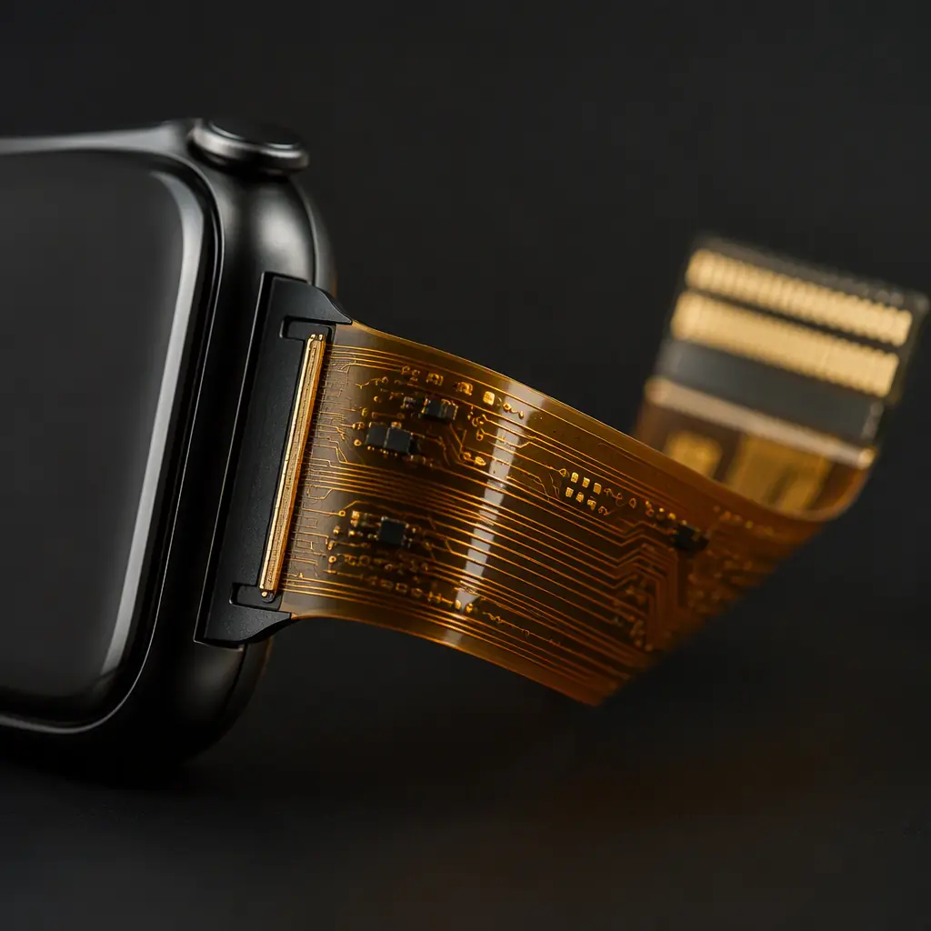
A smartwatch, a fitness band, a medical patch: every wearable shares the same constraint: it must be small, light, and flexible enough to conform to a wrist or chest, while enclosing electronics that would normally live on a stiff board. The flexible printed circuit (FPC) is what makes that possible, and it is also the component most likely to fail if the design ignores the mechanics of repeated bending.
The design problem is not just electrical, it is mechanical and thermal. A wearable PCB typically wraps around a curved casing, takes a fatigue load every time the user moves, and runs sealed in a housing where heat escapes through the strap rather than a heat sink. Huaxing PCBA builds these on flex and rigid-flex lines down to 0.3 mm pitch and 0201 components, with laser-drilled microvias supporting thin, many-layer flex.
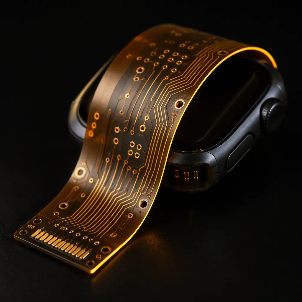
Why Wearables Need Flex Or Rigid-Flex
Rigid FR-4 does not fold. For a device that has to hug a wrist, you have three real options: a flexible board that bends, a rigid-flex hybrid that puts rigid islands where components sit and flex neck sections between them, or multiple rigid boards joined by flex. Each has a trade-off in cost, reliability and thickness.
Full Flex Saves Space And Mass
Polyimide flex is 0.1–0.2 mm thick in a single layer versus roughly 1.6 mm for a standard rigid board. That frees volume for the battery and lets the board itself wrap around the casing, which is exactly what a band-style wearable needs. See our flex PCB design guide for materials and layers.
Rigid-Flex Balances Stiffness And Flexibility
Components such as a display driver, SoC and battery connector cannot take repeated strain, so they sit on rigid islands with copper pads while flexible neck sections handle the bends. The result is a single board that folds and solders like multi-board without the connector joints. See our rigid-flex guide.
It Improves Reliability By Removing Connectors
Every board-to-board connector is a potential cold-solder or fretting failure in a moving device. By making the whole signal path one continuous flex, you remove that failure mode, a real durability win for a product that gets banged around. That logic applies to many compact products, not only wearables.
Bend Radius And Dynamic Flex Rules
Repeated bending is the leading cause of flex failure, traces and the plated holes that cross the bend zone crack over time. The rules here are mechanical, and they are non-negotiable.
Minimum Bend Radius Scales With Thickness
For a single-sided or two-layer flex, the minimum static bend radius is typically 6–10× the board thickness; for dynamic flex that sees tens of thousands of cycles, push to 15–20×. A 0.2 mm flex therefore wants at least a roughly 1.2–2.0 mm radius, and preferably more in a dynamic application.
Route Traces Perpendicular To The Bend
Copper is ductile, but it fractures at the edge where the trace crosses the strain zone. Route the traces parallel to the bend line where possible, and never run wide, heavy-copper traces straight across the bend centreline. See our trace sizing guide.
Keep Vias And Plated Holes Out Of The Bend
Plated through-holes and microvias are the weakest point in a flex bend, the barrel cracks first. Move all vias at least a few millimetres away from the bend zone, and if you must have them, consider a smaller tool and a stub-free design. Our via guide covers the trade-offs.
Layer Stackup And HDI Microvias For Thin Boards
Wearable electronics are dense. A health band packs a SoC, an optical heart-rate sensor, a display driver, PMIC and a battery charger into a board the size of a thumbnail. That density is achieved with thin layers, blind/buried vias and microvias.
| Stackup Element | Typical Wearable Value | Why It Matters |
|---|---|---|
| Layers | 2 – 8 (flex/rigid-flex) | Balances density with flex stiffness |
| Substrate | Polyimide 25–50 µm | Thin, heat-stable, flexible |
| Microvia | 0.075 mm laser | High routing density in thin layers |
| Line width | 3/3 mil | Fine-pitch SoC and sensor fan-out |
| Surface finish | ENIG (gold over nickel) | Good wire-bonding / solderability |
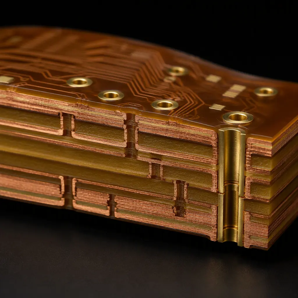
Use HDI For The Density
Blind, buried and laser microvias let you pack interconnects into far fewer layers than a conventional through-hole stackup. Our HDI technology guide walks through when any-layer interconnect becomes worth the cost.
Match The Substrate To The Flex Requirement
Polyimide is the default for its stability and flexibility. Where you need a stiffer region, rigid FR-4 islands are laminated into the same board. See our substrate comparison for the trade-offs.
Watch The Coverlay, Not Just The Copper
Flex uses a coverlay (flexible solder mask) which is softer than rigid solder mask. It protects the traces but also moves with the board. Aperture registration is critical, imprecise coverlay openings cause exposed traces or solder bridges. Our solder mask guide covers the types.
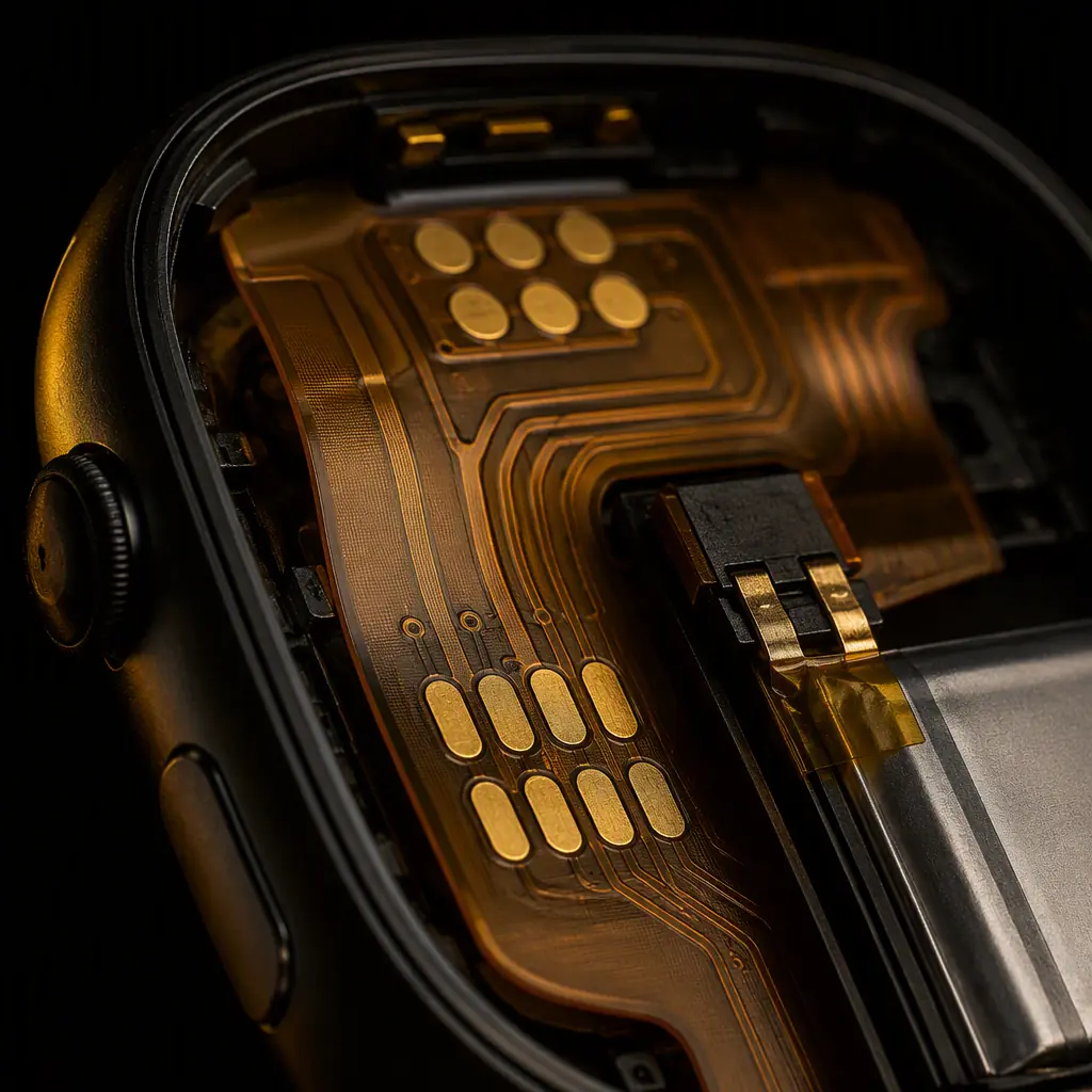
Sealing, Low-Power And Environmental Survival
Once the board is sealed in a wristwatch or a chest strap, the environment does the rest: sweat, rain, dust, humidity, temperature swings, and the occasional drop. The design has to survive all of it.
Conformal Coating For Moisture And Corrosion
Even inside a sealed housing, condensation can reach the PCB. A conformal coating protects against moisture and mild chemical attack, and on a flex it must be flexible enough to move with the board. See our conformal coating guide.
IP67 Sealing Is More Than The Gasket
Ingress protection is rated at the housing level, but the board must tolerate the sealing process, the potting, the encapsulation, and the heat of the final assembly. Robust pads, generous clearance and a sealed connector (via a dedicated sealing ring) are the board-side contributors. See our potting and encapsulation guide.
Design For A Few Milliwatts
A wearable battery is tiny, and the board quietly draws current 24/7. Choose a low-power PMIC, keep the DC/DC loop tight, and minimise leakage paths in layout. Some health devices also need the heart-health leads carefully routed for physiological signal integrity, a common ground to the sensor region matters.
Assembly Considerations For Thin Flex
Thin, flexible boards behave differently on an SMT line than a stiff 1.6 mm board. Tooling, support and panel strategy are the difference between a clean run and missing/rotated components.
Panel And Support During Handlers
Flex needs carrier support to stay flat through print, placement and reflow. Tooling holes and a rigid carrier keep the panel from sagging, which matters for fine-pitch placement accuracy. Our design-for-assembly guide covers panel layout.
Fine-Pitch, Miniature Components
0201 passives and 0.3 mm pitch packages are routine but unforgiving, pastest volume, pick accuracy and reflow profile all matter. See our fine-pitch assembly guide and stencil design guide.
Gold Finger And Connector Reliability
Where the flex mates to a battery or another board, electroless nickel immersion gold (ENIG), hard gold or a plated finger with extra plating gives a reliable, wear-resistant contact. Pair with a strain relief so the conductor does not flex right at the connector. See our gold plating comparison.
Summary, Building The Wearable Board
Design the flex as a mechanical member: respect the bend radius scaled to the flex thickness, keep vias and heavy traces out of the bend, and use rigid islands for components that cannot take strain. Layer up with HDI microvias where density demands it, seal and coat for the environment, and build on a supported carrier so the thin board stays accurate in assembly.
At Huaxing PCBA we manufacture flex and rigid-flex boards down to 0.075 mm laser microvias and 0.2 mm total thickness, assembled on 8 SMT lines placing 0201 and 0.3 mm pitch components, with IATF 16949 and ISO 9001 quality systems and conformal coating available. We offer a free DFM review of the flex bend-zone layout, stackup and assembly plan of your wearable. Send your Gerber and BOM for a quote or talk to an engineer about your wearable project.
