

Wave soldering is the oldest automated mass-soldering process still in daily production, and it is also the one most often run on inherited settings. A line that produced good boards last year keeps producing them this year right up until a supplier changes flux chemistry, the alloy pot picks up copper, or the preheat zone drifts — and then a batch of boards ships with bridges and unfilled barrels that look fine at a glance. The defect is not mysterious; it is one of five parameters crossing out of its window.
For a buyer, the important thing is that these five parameters are specifiable. You can put a control requirement on the purchase order and audit against it. That turns "the supplier says the yield is good" into an objective question — what flux solid content, what preheat top-side temperature, what contact time, what wave height, and how the alloy pot is monitored for contamination.
This guide sits alongside our broader PCB assembly process overview, the comparison of wave versus selective soldering, and the reflow-side counterpart covered in reflow oven profiling. Where reflow is a batch thermal profile, wave soldering is a continuous thermal-mechanical event — the board is contacted by molten metal, and the physics of that contact dominate the outcome.
At Huaxing PCBA we run wave soldering on 6 production lines under IATF 16949, with flux chemistry, preheat, conveyor speed, wave height and pot contamination logged as process parameters rather than operator judgement.
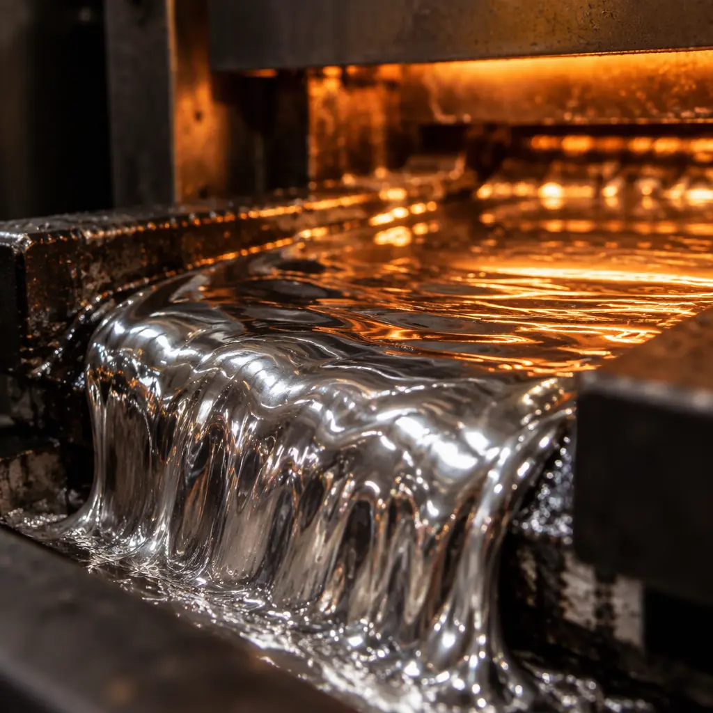
Parameter 1 — Flux: Chemistry and Application Volume
Flux removes oxide and prevents re-oxidation during the few seconds the joint is in contact with the wave. If flux fails, solder will not wet, and no amount of profile tuning recovers it. Two variables matter: chemistry and applied volume.
The three main chemistries behave differently on the wave. Rosin-based (RMA) fluxes are the most forgiving and wet the most aggressively, but they leave residues that normally require cleaning. Water-soluble (OA) fluxes give the best wetting and are fully cleanable, but their residues are conductive and corrosive if cleaning is incomplete. No-clean fluxes leave benign residues and dominate modern production, at the cost of a narrower process window — they tolerate less preheat abuse and less contamination. Our guide to flux chemistry selection covers the trade-offs in full.
Applied volume is where most flux problems actually live. Too little flux and the board de-wets at the wave, producing skips and incomplete fill. Too much flux and volatiles flash off violently in the preheat zone, spattering and leaving sticky residue that traps debris. The practical control is flux specific gravity or acid number, checked at the start of each shift, plus spray fluxer flow rate and air pressure logged per run. Alcohol-based fluxes change specific gravity as the solvent evaporates from the reservoir — a flux that reads 0.850 g/cm³ at shift start can drift to 0.870 by mid-shift, which is a real change in solids content.
Key Takeaway: Flux specific gravity or acid number is a shift-start verification, not a set-and-forget. A drifting flux reservoir is the single most common cause of "the wave suddenly stopped wetting" complaints.
Parameter 2 — Preheat: Top-Side Temperature Is the Controlled Variable
Preheat drives off flux solvent and brings the board and its through-hole barrels to just below soldering temperature, so the wave only has to supply the final increment of heat. It is the parameter most often mis-set, because it is usually set on the wrong measurement.
Preheat is normally specified as top-side board temperature, not heater setpoint. Heater setpoint tells you what the radiators are doing; top-side temperature tells you what the board is doing. For most no-clean fluxes the target is roughly 90-110 °C top-side for a standard 1.6 mm board, with the ramp staying within the flux's activation window. Too cold and solvent flashes at the wave, causing spatter, blowholes and solder balls. Too hot and the flux activator is consumed before the board reaches the wave — the flux is "used up" and wetting fails even though flux was correctly applied.
| Flux Type | Typical Top-Side Preheat | Failure if Too Low | Failure if Too High |
|---|---|---|---|
| No-clean (low solids) | 90-105 °C | Spatter, solder balls, blowholes | Activator consumed, poor wetting |
| Water-soluble (OA) | 95-115 °C | Solvent flash, voids | Oxide re-forms, skips |
| Rosin (RMA) | 85-105 °C | Excess residue, spatter | Reduced activity, icicles |
| Thick board (>2.0 mm) | 110-125 °C | Insufficient barrel fill | Flux burnout, cold joints |
The board thickness interaction is important. A 2.4 mm backplane needs more preheat than a 0.8 mm control board because the barrels are longer and the thermal mass is larger. Running both on one recipe is a common source of insufficient fill on the thicker board. Board preheat should be verified with a contact thermocouple or profiling pallet per product family, not extrapolated from a similar board.
Parameter 3 — Contact Time and Conveyor Speed
Contact time is the dwell during which the board's underside is in the wave, and it is set by conveyor speed over the wave's physical length. The typical window is 2-4 seconds of contact for a single-wave machine, though dual-wave machines split this between a turbulent chip wave and a smooth main wave.
Too little contact time and the barrel does not reach soldering temperature at the top — you get a fillet that looks complete on the solder side but fails to fill the barrel, which is the classic "insufficient fill" defect and is a genuine field-failure risk because the electrical connection is partial. Too much contact time overheats the board, lifts lands on thermally sensitive laminates, and produces excess dross. It also increases the thermal load on the mask and can cause mask blistering near the wave.
Conveyor speed must be set with the wave's actual contact length, not a nominal figure — the usable wave length changes if the pump is running slow or the nozzle is partially blocked. Speed is also affected by the conveyor's inclination angle, typically 5-7° for wave soldering, which determines how quickly a joint drains as it leaves the wave. A steeper angle drains faster (fewer bridges, but a higher risk of icicles); a shallower angle holds solder longer (better fill, more bridging).
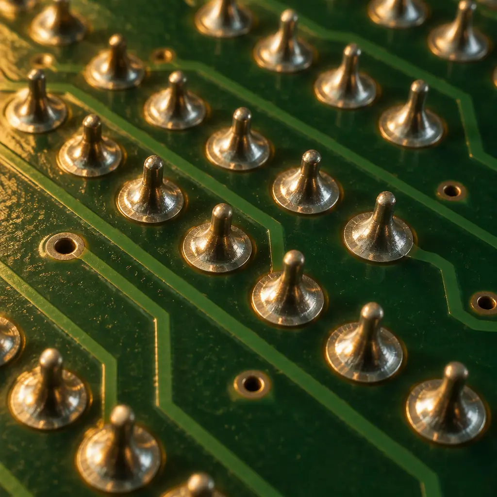
Parameter 4 — Wave Height, Turbulence and Dross
Wave height is the depth of the contact between the board and the solder surface. It must be held so the wave touches the board across its full width without flooding over the top side of the board or the pallet edges. A wave that is too low contacts intermittently, producing skips at the conveyor's edges; a wave that is too high pushes solder onto the component side and can deposit on parts that should never see solder.
The chip wave or turbulent wave on a dual-wave machine exists specifically to penetrate tight spaces and push flux gases out of plated barrels before the main wave fills them. Setting the chip wave too low negates its purpose; setting it too high agitates the pot and generates excess dross.
Dross is the oxide layer forming on the molten solder surface — an unavoidable byproduct that becomes a defect source when not controlled. Excess dross gets carried onto boards as dark, non-wetting contamination, and it also changes the wave's flow characteristics. Practical controls: keep the wave height stable, limit wave turbulence, use nitrogen inerting where the defect rate justifies the cost, and remove dross on a fixed schedule rather than when someone notices. Nitrogen reduces dross formation and improves wetting, at the cost of gas consumption and a slightly more complex machine setup.
Key Takeaway: Dross is not just a housekeeping issue. Dark, poorly wetting spots on joints and random non-wetting patches are frequently dross contamination, not a flux or profile problem.
Parameter 5 — Alloy Condition: Pot Contamination and Composition
The solder pot is a consumable that degrades continuously. Every board that passes through adds copper (from pad and lead dissolution) and, if the process is not controlled, other metals from leaded components, plated finishes and contaminated scrap. The pot composition is not constant even when the incoming bar stock is certified.
Copper pickup is the dominant contamination in SAC305 pots, because copper dissolves readily into tin-rich alloys. As copper rises the liquidus temperature of the alloy rises, so a pot that started eutectic slowly becomes pasty, and joints that used to flow cleanly start showing icicles, bridging and rough, grainy fillets. Industry guidance commonly places the copper ceiling at around 0.30-0.35 wt% for SAC305, above which the alloy should be diluted with pure tin or partially replaced. A pot that is never analysed is a pot that is slowly drifting out of specification.
Verifying alloy composition is a laboratory exercise — either by optical emission spectrometry on a pot sample or by X-ray fluorescence on solidified solder. This is the same verification discipline that applies to incoming solder bar and paste; our guide to RoHS compliance covers the broader declaration framework that alloy verification supports.
| Contaminant | Typical Ceiling (SAC305) | Observed Symptom |
|---|---|---|
| Copper (Cu) | 0.30-0.35 wt% | Icicles, bridging, grainy fillets |
| Iron (Fe) | 0.02-0.03 wt% | Reduced flow, rough surface |
| Lead (Pb) | 0.05-0.10 wt% (RoHS) | Raises liquidus, non-compliance risk |
| Zinc (Zn) | 0.003 wt% | Non-wetting, poor filleting |
| Cadmium (Cd) | 0.002-0.005 wt% | RoHS failure |
Pot analysis frequency is a supplier-discipline question a buyer can specify. Good practice is a documented analysis interval — monthly for a high-throughput line, quarterly for a low-volume one — with the results retained and available on request, plus a defined action level at which the pot is diluted or replaced. A supplier who cannot produce a recent pot analysis is running on assumption.
What to Specify on the Purchase Order
The five parameters translate into a small number of contract-level requirements. Specifying them costs nothing and makes the process auditable:
Flux chemistry and solids content
Name the flux class (no-clean, water-soluble or rosin) and require the supplier to declare the specific chemistry. For no-clean, state the maximum residue level acceptable without cleaning.
Preheat verification method
Require top-side board temperature to be verified by contact thermocouple or profiling pallet per product family, with readings retained. Not heater setpoints.
Barrel fill acceptance criteria
State the fill requirement by barrel — commonly 75% minimum fill for Class 2 and higher for Class 3 — and require the supplier to demonstrate it via microsection on the first article.
Pot alloy analysis and interval
Require documented composition analysis at a stated interval, with the results available on request and a defined copper action level.
Dross and pot maintenance schedule
Ask for the dross removal and pot cleaning interval, and for the machine's preventive maintenance record at audit.
Wave Versus Selective: Choosing the Right Process
Wave soldering is not always the correct answer for through-hole content. Boards with a small number of through-hole connectors, boards with mixed SMT and through-hole on the same side, and boards with thermally sensitive parts are usually better served by selective soldering, which applies solder to one joint at a time with a mini-wave or point nozzle. Wave soldering wins on throughput and cost for boards with high through-hole density, simple geometry and a single wave-compatible side. Our dedicated comparison, wave versus selective soldering, walks through the decision by board type and volume. Getting this choice right at the start avoids the more common failure mode: forcing a selective-soldering board onto a wave line and chasing defects forever.
Closely related is the question of pin-in-paste reflow, which eliminates the wave entirely for boards where the through-hole content can be printed and reflowed with the SMT side. And for joints where thermal mass is the limiting factor, the fundamentals of solder joint defect analysis apply to wave and reflow alike.
The Bottom Line
Wave soldering failures are the most predictable in electronics assembly, because the process has only five levers. When a line starts producing bridges, icicles or insufficient fill, the diagnosis is mechanical: verify flux condition, verify top-side preheat, verify contact time against actual wave length, verify wave height and dross state, and verify pot composition. In practice the answer is nearly always flux drift, preheat measured at the wrong point, or a pot that has quietly picked up copper.
For a buyer, the lever is upstream of the defect. Put flux chemistry, preheat verification, barrel fill acceptance and pot analysis on the purchase order, and the supplier's process becomes something you can audit rather than trust. Our team runs wave soldering across 6 lines with full parameter logging and documented pot analysis, and we are happy to share the process control plan for your assembly.
For a full picture of how wave soldering integrates with the rest of the build, see our turnkey PCB assembly overview and the control plan and PFMEA guide that documents how these parameters are held in process.
