

A control plan is a document that says, for every step of a manufacturing process, what characteristic must be controlled, how it will be measured, how often, and what happens when it goes out of control. On its own it looks like bureaucracy. In practice it is the difference between a factory that reacts to defects and one that prevents them, because it names the controls at each step before the first board is built.
For a PCB buyer, the control plan is also a diagnostic tool. It tells you whether a supplier has actually thought about where its process fails — or is simply promising good quality without a mechanism. A control plan that pairs with a real PFMEA is evidence of process understanding; a generic template with the customer's part number pasted in is evidence that someone is going through the motions. Knowing the difference is worth the read, and it is the reason this document shows up as a required element of PPAP.
At Huaxing PCBA we build control plans for production programmes across 8 SMT lines under IATF 16949 and ISO 9001, developed from a PFMEA rather than a template. This guide describes how that package is built and what to look for when you review one.

What a Control Plan Is and Where It Sits in APQP and PPAP
The control plan is one document in a chain. APQP — Advanced Product Quality Planning — is the overall framework for launching a new product; PFMEA is the risk analysis of the process; the control plan is the operational summary of how those risks are controlled in production. The three are linked: the control plan's content comes directly from the PFMEA's high-risk items.
In PPAP, the control plan is a required element. It sits alongside the process flow diagram and the PFMEA as the trio that defines how the process will be controlled. When a buyer approves a PPAP package, they are approving not just a sample part but the system that is supposed to keep producing parts to that standard. A control plan with no link to a PFMEA, or one that copies generic steps without this product's characteristics, tells you the system is thin.
The document itself is a table. Each row is a process step; each row records what is being controlled at that step and how. The discipline is in making each row specific to the actual process and the actual failure risks — which is why the PFMEA comes first.
PFMEA First: Identify What Can Fail
A process FMEA asks, for each process step, what could go wrong, how bad the effect would be, how likely it is to occur, and how likely the current controls are to catch it before it escapes. The classic scoring multiplies severity, occurrence and detection into a risk priority number, and the modern AIAG-VDA approach adds an Action Priority that weights severity more heavily — a step with a severe, hard-to-detect failure gets attention even if its RPN is moderate.
For a PCBA line, the failure modes are well known, which is an advantage: you are not inventing risk, you are confirming which risks apply to this board. The library below covers the modes that matter most on an SMT line.
| Process Step | Failure Mode | Effect |
|---|---|---|
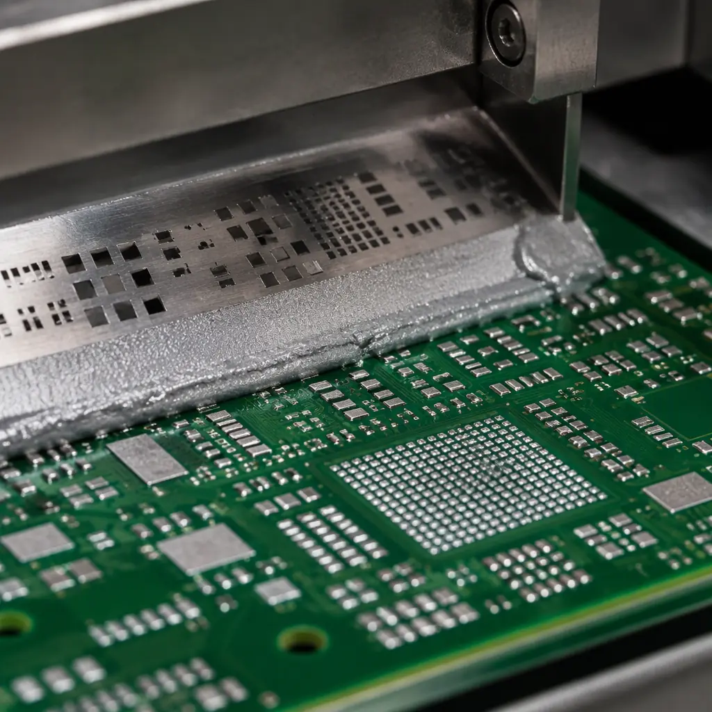
| Solder paste printing | Insufficient / excess paste volume, misalignment | Opens, bridging, weak joints |
| Component placement | Wrong part, wrong orientation, offset, tombstoning | Non-functional board, field failure |
| Reflow | Excess voiding, cold joint, thermal damage | Intermittent or latent failure |
| Handling / ESD | Static damage to components | Latent failure, early-life returns |
| Test | Escape past a test gate, false pass | Defective board shipped |
The output of the PFMEA is a list of high-risk items — the ones that feed the control plan. A mode with high severity and high occurrence but no effective detection is exactly where a control plan earns its keep.
The Control Plan Columns and What Each Means
Every line item in a control plan answers the same seven questions. If any column is vague, the control is not real.
Process step and product / process characteristic
Which step of the flow, and what exactly is being controlled — paste volume, placement accuracy, reflow peak temperature, ESD wrist-strap continuity. "SMT process" is not a characteristic; "paste deposit volume per pad, expressed as a percentage of target" is.
Specification and tolerance
The numeric target and the limits outside which the part or process is not acceptable. Tolerances come from the design, the IPC standard, or the customer's drawing — they are not invented at the machine.
Evaluation / measurement method
How the characteristic is measured — SPI for paste volume, AOI for placement, thermocouple profiling for reflow, a daily ESD check for handling. This column links the control to the equipment that proves it.
Sample size and frequency
How many and how often — 100% for AOI, first-article plus periodic for profiling, a fixed sample per shift for a destructive check. Frequency is a cost decision matched to the risk the PFMEA identified.
Control method
What physically prevents or detects the failure — a machine parameter lock, a poka-yoke fixture, an automatic reject at inspection. A control that relies on an operator remembering is the weakest kind.
Reaction plan
What happens when the characteristic goes out of control: contain the affected product, quarantine back to the last known-good point, root-cause, correct, and verify. A control plan without a reaction plan is a measurement plan, not a control plan.
The seventh question — who owns the control and what record proves it — runs across the document. Every control should leave a trace: an SPI log, an AOI record, a profiling chart. Evidence is what makes the plan reviewable.
A Worked PCBA Control Plan
The table below is the skeleton of a control plan for a typical SMT line. It is deliberately concrete, because the value of the document lives in the specifics of each row.
| Step | Characteristic | Method | Sample | Reaction |
|---|---|---|---|---|
| Paste print | Deposit volume, area, alignment | SPI | 100% | Clean stencil, adjust, re-inspect |
| Placement | Part identity, polarity, offset, rotation | AOI pre-reflow | 100% | Rework before reflow |
| Reflow | Peak temp, time above liquidus, ramp | Thermocouple profile | Daily + per change | Stop line, re-profile, quarantine |
| Post-reflow | Solder joint quality, voids | AOI + X-ray | 100% AOI, X-ray per plan | Rework or scrap at disposition |
| Electrical test | Continuity, values, function | ICT / flying probe / FCT | 100% | Rework, retest, log a failure |
| Handling | ESD control, MSL exposure | Daily wrist-strap / ioniser check, MSL log | Daily + per lot | Stop, correct, re-qualify station |
Key Takeaway: The reaction plan is where a control plan proves it is real. A row that defines the control but not what happens when the control fails describes a measurement, not a control. When you review a supplier's control plan, read the reaction column first.
Note how each row links to a specific piece of evidence. Paste print is proved by SPI data; reflow by a profiling chart; electrical test by a test log. If a supplier cannot show you those records, the controls on the plan are claims rather than controls. The inspection methods themselves are covered in our AOI, X-ray and SPI inspection guide, and the paste-volume control this plan's first row relies on is detailed in solder paste volume control with SPI.

How the Control Plan Lowers Buyer Risk — and What to Demand at PPAP
The control plan lowers risk in a way that is easy to miss: it moves quality from inspection at the end to control at the source. A process controlled at the paste printer does not produce the defects that the end-of-line test would have to catch. Fewer defects created means fewer escapes possible, and a lower cost of quality overall.
When you receive a PPAP package, three things in the control plan are worth checking closely. First, does each control link back to a PFMEA item — is the plan responding to an identified risk, or is it a generic template? Second, are the frequencies and reaction plans specific to your product and its volume? Third, does the supplier actually keep the records the plan implies — ask for a sample of SPI, profiling and test logs from a previous run.
A plan that names the right characteristics and frequencies, backed by real records, is a strong signal. A plan that lists "visual inspection" for every row with no reaction plan is a template, and templates protect the supplier's paperwork, not your product. The wider evidence package around this is described in our PPAP for PCB assembly guide.
Common Mistakes
Control plans fail in predictable ways, and recognising them is most of the review skill.
Copying a template without the PFMEA. A plan that was not built from a process risk analysis cannot be responding to real risks, because nobody identified them first.
Vague characteristics. "Good solder joints" and "proper placement" are opinions, not tolerances. Every characteristic needs a number or a standard reference.
No reaction plan. The most common gap. A control that detects a problem but does not define containment and correction lets defective product flow while the problem is discussed.
100% inspection as a substitute for control. Adding inspection to catch a defect the process keeps producing is expensive and unreliable compared to fixing the process at its source — which is what the PFMEA was supposed to identify.
Never revised. A control plan is a living document. When the process changes or a defect escapes, the PFMEA and control plan should both be updated. A plan untouched for years has stopped describing the process. The yield data these controls feed is examined in our SMT first-pass yield diagnosis guide, and the output side in outgoing quality control.
What Huaxing PCBA Provides
At Huaxing PCBA we develop the PFMEA and control plan per production programme across 8 SMT lines under IATF 16949 and ISO 9001, tied to our SPI, AOI, X-ray and electrical test controls rather than a generic template. For buyers who need a PPAP package, the control plan is provided with the process flow and PFMEA behind it and with the inspection records the plan implies. A worked test-coverage plan that sits alongside the control plan is described in our PCBA test strategy guide.
If part of qualifying a supplier is seeing how they think about their own process, the control plan is the fastest way to find out — and the right time to ask is before production, not after an escape.
Send your Gerber and BOM with your PPAP and control-plan requirements and we will confirm the quality package we can provide and return a quote inside 24 hours, or talk to our engineering team about the control plan your programme needs.
