
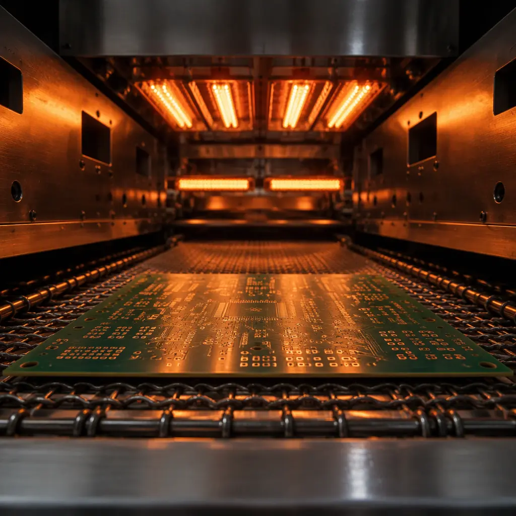
A reflow oven is the one piece of SMT equipment whose quality is entirely invisible from the outside. It sits in the line, zones glowing, and a completed profile on file proves nothing on its own — a profile is only evidence if you know which board it was measured on, how the thermocouples were attached, and what window it was judged against. A supplier can run a perfect profile for one board and then run a completely different thermal mass through the same recipe and call it qualified.
For a buyer, reflow profiling matters because it sits between two defect families. Upstream, it interacts with the paste and the print quality; downstream, it produces or prevents voids, incomplete joints, tombstoning, warpage and damage to sensitive components. When reflow is uncontrolled, the defects it generates are frequently blamed on the paste, the stencil or the components — and the wrong fix is applied. Understanding how a profile is built and judged is what lets a buyer ask the right question.
This guide sits inside the SMT process series alongside our pages on nitrogen reflow and O2 control and reflow profile optimization, and it connects to the defect side covered in solder joint defects. It is written for the buyer or hardware manager who needs to tell real thermal process control from a filed piece of paper.
At Huaxing PCBA we profile reflow per board family across 8 SMT lines under IATF 16949 and ISO 9001, with thermocouple attachment validated against the board's own thermal mass and the resulting profile stored with the production traveller rather than in a folder of generic recipes.

What a Reflow Profile Is Made Of
A reflow profile is the temperature-versus-time curve a specific point on the board experiences as it travels through the oven. It is not the same as the oven's zone setpoints — the zone temperatures are inputs, and the profile is what the board actually sees, which depends on thermal mass, board thickness, copper content and component loading. That gap between setpoint and actual is the reason profiling is a measurement, not a setting.
The curve has four phases, and each does a distinct job:
Preheat. The board is brought up toward the soak temperature at a controlled rate, typically a few degrees per second at most. The purpose is to warm the assembly without thermal shock and to begin activating the flux. Ramp rate here is an important setting: too fast and you risk cracking thermally stressed components and spattering flux; too slow and the process wastes cycle time.
Soak (or soak zone). The board is held at an intermediate temperature — commonly in the range from about 150 °C to 180 °C for a SAC305 process — long enough to bring the whole assembly, including large thermal masses and shielded areas, to a uniform temperature and to fully activate the flux and drive off volatiles. This is the phase that equalises the board, and it is where the difference between a thermally uniform and a thermally patchy board shows up.
Reflow. The board is taken above the alloy's liquidus so the paste melts, wets and forms the joint. For SAC305 the peak is typically in the range of 235 °C to 250 °C, with the time above liquidus (about 217 °C for SAC305) held within a defined window — usually tens of seconds. Peak temperature and time above liquidus together determine whether the joint fully forms without over-stressing components.
Cooling. The board is cooled at a controlled rate. Cooling controls the grain structure of the joint — a very slow cool can produce a coarse, weaker microstructure, while a very fast cool risks thermal shock. The cooling rate is a real process variable, not just a cooldown.
Soak vs Ramp: Which Board Wants Which
There are two well-known profile families — ramp-to-spike (RTS) and ramp-soak-spike (RSS) — and the choice between them follows from the board's thermal behaviour, not fashion.
Ramp-to-spike (RTS) rises steadily from preheat through to peak with a straight ramp, no distinct soak plateau. It suits boards that are thermally uniform — thin, lightly loaded, or with components of similar mass — where a steady ramp brings everything up together. The advantage is a shorter, simpler profile; the risk is that on a board with mixed thermal mass, the small parts reach reflow while the larger masses are still cold.
Ramp-soak-spike (RSS) inserts the soak plateau between ramp and spike. The plateau gives heavy components and large copper areas time to catch up to the small ones, so that when the spike arrives, the whole board is closer to a uniform temperature. It suits thermally non-uniform boards — thick, high-layer-count, heavy-copper, or carrying both large and small components. Most complex B2B boards favour RSS for exactly this reason.
The practical point for a buyer is that a supplier running one generic profile for every board is running RSS or RTS where it does not fit for at least some of them. The profile should be matched to the board's thermal mass, and the way to verify that is to see the thermocouple data for that board — not a global recipe.
Key Takeaway: RTS suits thermally uniform boards; RSS suits boards with mixed thermal mass, which describes most multi-layer, mixed-component production boards. A single profile applied to every board is a sign the profiling was not done per board family.
Thermocouple Setup: Where Profiling Usually Fails
The profile is only as good as the thermocouple measurement behind it, and thermocouple attachment is the step most often done poorly because a bad attachment still produces a plausible-looking curve. Four things must be right.
Location. Thermocouples must be attached at the locations that matter thermally — not arbitrary points. Typical practice is to attach at the solder joints of the largest thermal mass, the smallest fine-pitch components, the board centre and edge, and any large shielded component. The measured profile must include the point that will be slowest to heat, because that is the point that governs whether the paste reaches reflow everywhere.
Attachment method. The thermocouple junction must be in intimate contact with the measured surface. High-temperature adhesive, a small spot of high-temp solder, or a purpose-made attachment is used — tape alone, or a bead floating off the surface, measures air temperature rather than board temperature and produces an optimistic curve. This is the single most common defect in profiling.
Adequate thermocouple gauge. The wire should be thin enough not to act as a heat sink that pulls the joint's temperature down, and the junction should not be so large that it lags the actual surface. Fine-gauge thermocouples are used for exactly this reason.
Instrumentation and logging. A profile is recorded by a datalogger that travels through the oven with the board, capturing the curve at each thermocouple. The recorded data — not just a summary peak — should be kept as the evidence, because it is the curve shape and the time-above-liquidus that a process window is judged against.
Process Windows and the PWI
Once a profile is measured, it has to be judged against something. The tool for that is the process window: a defined range for each profile parameter, within which the process is known to produce acceptable joints. Typical window parameters include ramp rates, soak time and temperature, peak temperature, time above liquidus, and cooling rate.
The process window index (PWI) is a single number that expresses how far a measured profile sits from the centre of its process window, scaled by the width of each parameter's limit. A PWI of 0% means the profile sits at the perfect centre; 100% means it is at the edge of the window; above 100% means it has exceeded at least one limit. Because it normalises every parameter against its own window, the PWI lets a supplier judge a whole profile in one figure and compare profiles across different boards.
Guidance for reflow profiling — the temperature profiling methodology, window definitions and how to set them — is described in IPC-7530, the standard for temperature profiling in the reflow process. A buyer who asks "what is the PWI of this profile?" is asking a question that a supplier with real thermal control can answer immediately, and that a supplier without it will not.
Nitrogen and Its Interaction with the Profile
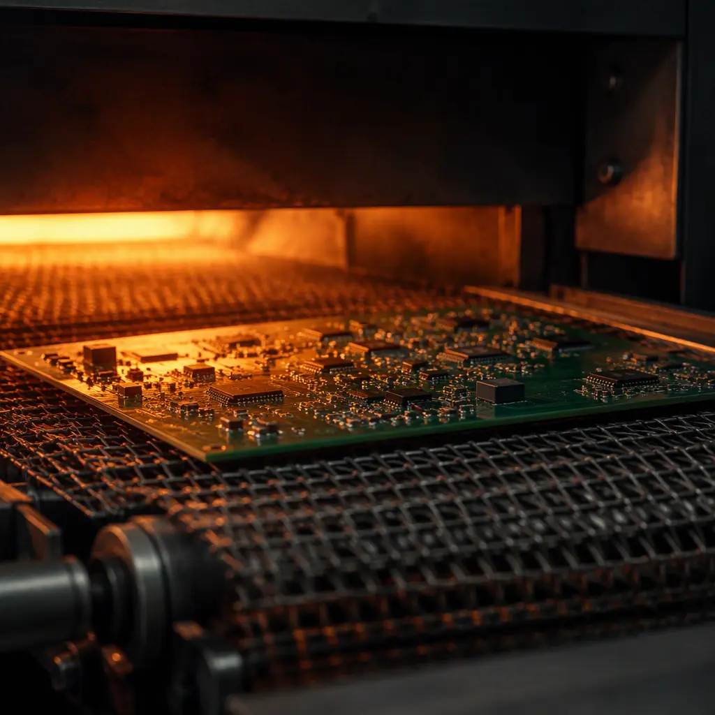
For higher-reliability or fine-pitch work, reflow is sometimes run under nitrogen to reduce oxidation of the molten solder and the pads. Nitrogen does not change the profile shape, but it changes what the profile can get away with: lower oxygen concentration improves wetting, which widens the effective process window and reduces the sensitivity of the joint to marginal peak temperature or time above liquidus. The trade-off is cost — nitrogen consumption rises sharply as the target oxygen concentration falls — and the decision of when nitrogen earns its keep is covered in our guide to nitrogen reflow and O2 targets.
Buyers evaluating a high-reliability build should treat nitrogen as a profile-quality partner rather than a separate feature: it is most valuable where the paste and component mix would otherwise leave the process window narrow.
What a Buyer Should Demand
Reflow process control is one of the easiest supplier claims to verify, because the evidence is a measurement. When auditing or qualifying a supplier, ask for:
A profile per board family, not a generic recipe. The profile should be identified with the board it was measured on, and matched to that board's thermal mass.
The thermocouple data, with attachment documented. The recorded curve and the attachment locations. A peak temperature figure without the curve is not the profile.
The process window and the PWI. The window limits the supplier manages to, and where the measured profile sits inside them.
Evidence the profile is re-verified. Profiles drift with oven condition, paste lot and board revision, so the re-verification interval — after oven maintenance, on a board revision change, on a paste change — should be defined.
Connection to defect data. A supplier that reports reflow-related defects against its profile data is closing the loop; a supplier that reports them without that link is guessing. This is the same discipline our guide to first-pass yield diagnosis describes on the yield side.
What an Out-of-Window Profile Produces
The reason to hold the profile inside its window is the specific defects that appear when a parameter drifts. A peak temperature that is too low or a time above liquidus that is too short produces incomplete joints and cold or weak solder. Too much heat or too long above liquidus produces excessive intermetallic growth, embrittlement and damage to sensitive components, and can drive voiding. A soak that is too short leaves the heavy masses cold when the spike arrives, producing the classic mixed picture of good small joints and poor large ones on the same board. A cooling rate that is too slow coarsens the joint microstructure.
None of these are decided by the paste or the stencil alone. They are decided by the profile — which is why a supplier that fixes a reflow defect by changing the paste, without looking at the profile, is often fixing the symptom and leaving the cause in place. The defect families themselves are catalogued in our guide to solder joint defects.
Summary: A Profile Is Evidence Only If You Can Audit It
Reflow oven profiling is a measurement of what a board actually experiences, and its value depends entirely on how it was measured and what it was judged against. The four profile phases — preheat, soak, reflow, cooling — have to be matched to the board's thermal mass through the choice of RSS or RTS. The thermocouples have to be attached so the measurement is real. And the resulting curve has to be judged against a process window, summarised as a PWI, with a defined re-verification interval. A supplier who can produce all of that for your board has thermal process control; one who produces a folder of profiles without the data, the attachment record or the window has a document, not a process.
At Huaxing PCBA we build reflow profiles per board family across 8 SMT lines under IATF 16949 and ISO 9001, attach thermocouples at the governing thermal locations, judge each profile against its process window, and store the recorded data with the production traveller. Send us your stackup and component mix and we will profile for it rather than for a generic recipe. Request a quote with a profiling plan and we will return it inside 24 hours, or talk to our process engineering team about a reflow question you are working through.
