
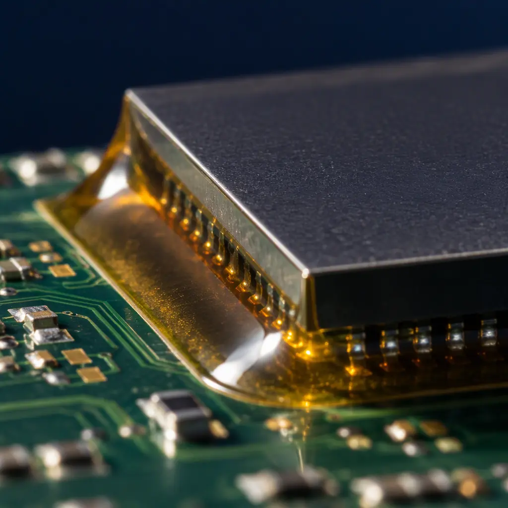
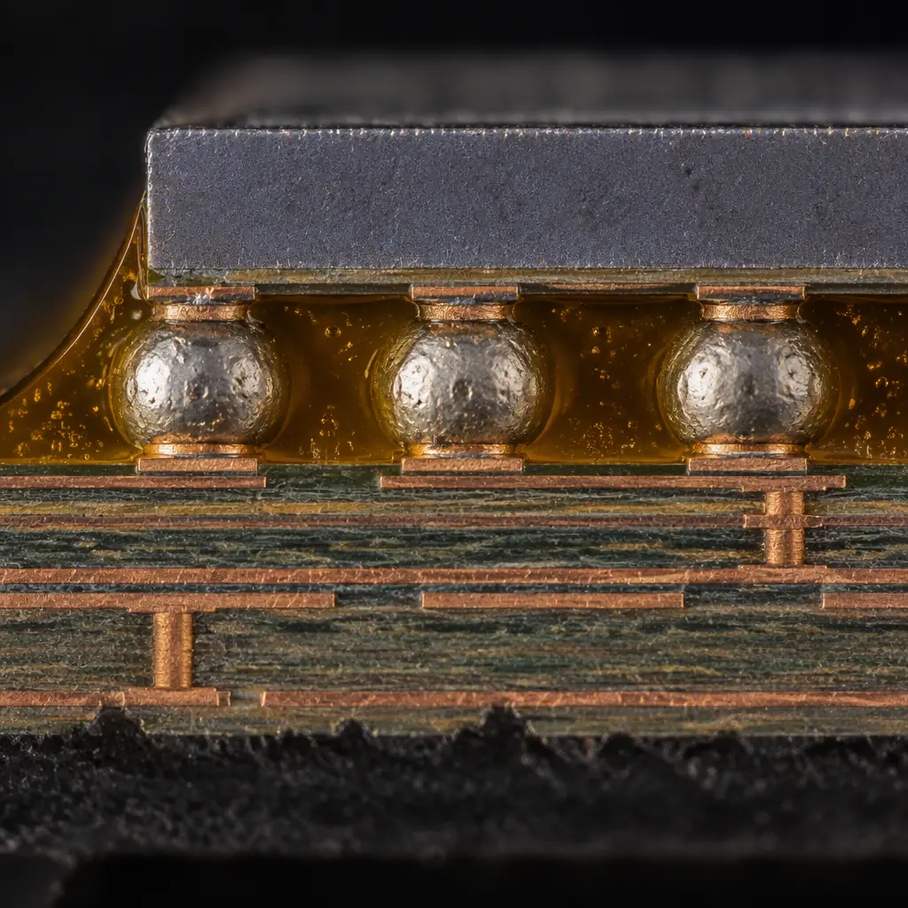
Underfill is specified for one reason: to spread the coefficient-of-thermal-expansion mismatch between a silicon die and an organic substrate across a compliant adhesive instead of concentrating it in the solder joints. For a large flip-chip, a CSP at fine pitch, or a board that will see thermal cycling in an automotive or industrial environment, that decision is usually correct and it is usually made early, often at the design-freeze review rather than at the process review.
The consequence becomes visible later. Once the underfill is cured, the component under it is no longer reworkable in the sense that a normally assembled BGA is reworkable. This is not a manufacturing defect, it is the intended behaviour of the material — which means the decision to underfill is also, implicitly, a decision about what happens when a board fails in test or in a customer's hands. Understanding exactly where that line falls is what separates a programme that can absorb an occasional failure from one that scraps an entire panel because a single IC is bad.
Why Cured Underfill Resists Removal
The difficulty is not that the adhesive is particularly strong in tension. It is that removal requires heating the assembly enough to soften the material, and the two things you need to protect — the solder joints and the laminate — both have thermal limits below the range where a fully cured epoxy flows.
A capillary underfill based on a filled epoxy typically reaches its glass-transition temperature somewhere in the 80 to 150 degrees Celsius band depending on formulation, and above that point it softens progressively but does not become a liquid you can simply lift away. To break the adhesive bond you generally need to approach or exceed the reflow temperature of the solder you are trying to preserve. At that point the solder joints are liquid, the component may float, and the substrate has absorbed enough heat cycles that its own reliability budget is partly spent.
| Underfill Type | Removability After Cure | Practical Method |
|---|---|---|
| Capillary epoxy, filled | Very low | Heat to above Tg with controlled hot air or a thermal stage, mechanical lift with low force; expect component and possibly pad damage |
| No-flow underfill | Low to moderate | Similar thermal approach, but the thinner fillet and lower filler content make lift somewhat easier |
| Molded underfill (MUF) | Effectively zero | Removal destroys the package; the die and its bond wires are encapsulated with the board |
| Corner bond / edge bond | Moderate to high | Localised adhesive only at the corners; heat and lift is feasible with less collateral risk |
| Parylene or conformal overcoat | Moderate | Not a structural underfill, but removal by mechanical abrasion or plasma is a separate process |
Key Takeaway: Molded underfill is a one-way decision. If a programme uses MUF, plan for whole-assembly replacement rather than component-level rework, and make sure the test coverage upstream is good enough that a bad part is caught before the underfill reaches the parts that cannot be recovered.
The Four Removal Routes and Their Real Cost
When removal is attempted, the industry uses four approaches. Each trades board survival against time, and none of them is clean.
Thermal softening with mechanical lift
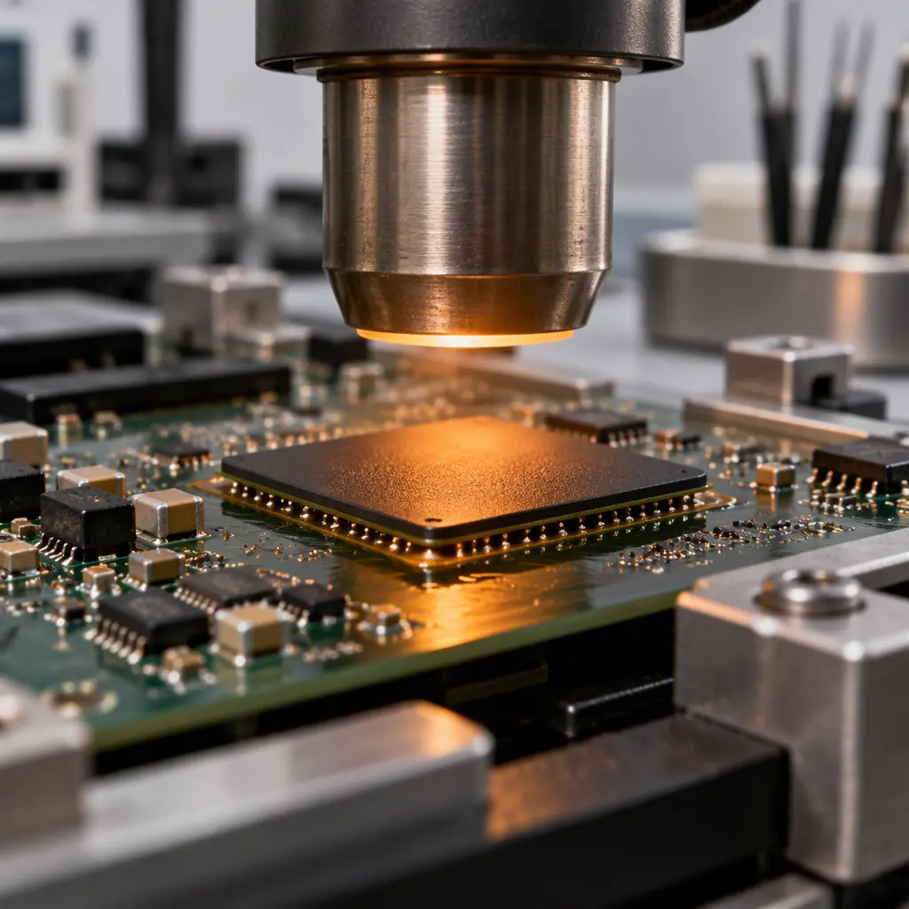
The standard route. The board is brought to a temperature above the underfill glass transition on a hot-air rework station or thermal stage, then the component is lifted with a vacuum nozzle using low, controlled force. The adhesive does not melt; it loses modulus and yields along the fillet. Success depends heavily on how much of the fillet is accessible and whether the surrounding area can tolerate the heat. Plan for 20 to 40 minutes per component by a skilled operator, and treat a 50 to 70 percent success rate as realistic rather than exceptional.
Localised mechanical milling or abrasion
For boards where heat is unacceptable — a denser assembly, a temperature-sensitive neighbour, a thick copper plane acting as a heat sink — the fillet can be milled away with a fine tool before thermal lift. This is slower, requires fixture support, and carries a real risk of nicking traces or the solder mask beneath the fillet. It is best reserved for large packages with an accessible perimeter.
Chemical swelling agents
Some epoxy underfills respond to proprietary swelling solvents applied as a gel or soak. Where a formulation is known to respond, this softens the fillet and reduces the mechanical force needed. The limitation is formulation-specific: an agent that works on one supplier's product may do nothing on another, and the soak time and worker-safety controls make it unattractive for anything other than occasional salvage. Always verify on a scrap board before committing a real assembly.
Package destruction and site rebuild
Where the component is inexpensive and the board is expensive, the practical answer is often to destroy the package mechanically, clean the site, and reball or replace. This is closer to board salvage than rework, and it demands that the pad and mask survive the extraction. Resin residue left on the pads is the usual failure mode, because incomplete cleaning produces a joint that looks acceptable and fails later.
What the Board Tells You Before You Start
Before attempting any underfill removal, three questions determine whether the operation is worth attempting at all. They should be answered from the design files and the process record, not from inspection of the failed board alone.
How much thermal budget does the laminate have left? A board that has already been through reflow twice, a selective soldering pass and an underfill cure has consumed part of its thermal history. Adding a removal cycle at or near reflow temperature risks delamination, measling and via barrel cracking that may not show until the board is in the field. Where the board is a high-layer-count, high-Tg part, one removal cycle is generally tolerable; where it is a thin, low-thermal-mass assembly that has seen multiple passes, it may not be.
Is there anything adjacent that cannot take the heat? The thermal profile needed to soften underfill is not localised in practice. A neighbouring component with a low moisture-sensitivity threshold, an already-populated area, an electrolytic capacitor or a plastic connector body all constrain the achievable temperature. Mapping the keep-out radius before starting is faster than discovering it during removal.
Is the failure actually in the underfilled component? This sounds trivial and is frequently skipped. A board that fails functional test with an underfilled CSP does not necessarily have a CSP problem; the fault may be in a neighbouring passive, a via, or a connector. Attempting removal on the wrong component converts a repairable fault into a scrapped assembly. Electrical localisation before thermal work is the cheapest step in the whole sequence.
Design and Process Choices That Preserve Reworkability
Most of the recoverability of a programme is decided before the first board is underfilled. Four choices consistently make the difference.
| Choice | Reworkability Impact | When to Take It |
|---|---|---|
| Partial underfill (corners only) instead of full capillary | High — corners can be heated and lifted locally | Board sees moderate shock and vibration but is not in a high-CTE-mismatch thermal-cycling regime |
| Edge bond or corner bond as first-line protection | High — adhesive is accessible and the component remains replaceable | Large-body packages where the dominant risk is board flexure during handling and depanelisation, not thermal fatigue |
| No-flow underfill instead of capillary | Moderate — thinner, less-filled fillet removes more easily | High-volume SMT where the process can tolerate the flux-compatibility constraints |
| Underfill only the critical components, not the whole board | High — leaves the rest of the assembly normally reworkable | Almost always, unless the whole assembly is in a severe environment |
The discipline that pays best is underfilling selectively. Boards are frequently fully underfilled because the process is set up once and applied everywhere, not because every component needs it. A board where only the two large flip-chips and the memory package are underfilled retains ordinary reworkability for the dozens of passives and small ICs that account for most field failures. This is a specification decision, made at design review, and it costs nothing to make correctly. The mechanics of how underfill is applied and how the dispense pattern controls voiding are covered in our guide to PCB underfill selection.
Setting the Rework Policy Before Production
The most expensive version of this problem is the one discovered mid-programme, when a customer asks why a failed underfilled board was scrapped rather than repaired and nobody can point to an agreed policy. The cheap version is a one-page policy agreed at the start, covering four decisions.
Procurement Tip: Agree four things in writing before the first underfilled production lot. First, which components are underfilled and which are deliberately left free — this defines what is reworkable. Second, whether underfilled-component failure results in component-level recovery or board scrap, and at what unit value the decision flips. Third, the maximum number of thermal cycles a board may receive, counted across assembly, rework and removal. Fourth, who authorises the scrap decision. A programme that answers these four questions at the outset never has an argument about it later, and the answers cost nothing to write down.
There is also a test-strategy consequence. If a component cannot be reworked, the value of catching its faults increases sharply. Coverage upstream of the underfill dispense — in-circuit test, X-ray of the joints before encapsulation, and functional test on the assembled-but-unfilled board — should be specified with that in mind. Board-level coverage that would be adequate for a fully reworkable assembly is often not adequate when the dominant failure mode leads to scrap. How that coverage is specified is set out in our guide to flying probe versus ICT versus functional test, and the joint inspection methods used before encapsulation are covered in AOI, X-ray and SPI inspection.
When Rework Is the Wrong Answer
There are cases where attempting removal is not merely hard but actively harmful, and recognising them protects both schedule and quality record.
Where the assembly is safety-critical and qualified under a functional-safety process, board-level rework after a thermal-cycle event may invalidate the qualification evidence unless it is performed under the same controlled conditions that produced the original. The engineering effort to re-qualify the rework usually exceeds the cost of the board. The same logic applies to medical assemblies where the process is validated as a whole; see our guide to IEC 60601-1 for medical PCBA for how validation scope interacts with rework.
Where the underfill was applied specifically to address a fatigue mechanism, removal and replacement rarely restores the original reliability. The new fillet will differ in volume, in cure history and in adhesion to a surface that has already been thermally cycled. The board may pass test and still carry a reduced life. Where the programme's reliability demonstration depends on that component, scrapping is the honest answer and should be the documented one.
The Bottom Line
Underfill is not an irreversible mistake, but it is a substantially irreversible process decision. Fully cured molded underfill cannot be removed in any useful sense; capillary underfill can sometimes be recovered at significant labour cost and with a real risk of collateral damage; corner and edge bonding preserve ordinary reworkability and cover a large part of the mechanical risk. The choice between them is made at design review, on the board layout and the environmental specification, and it is one of the decisions where a small amount of forethought is worth considerably more than a large amount of recovery effort.
At Huaxing PCBA we specify underfill selectively by component rather than board-wide, document which packages are encapsulated in the process record, hold capillary and no-flow underfill recipes with void-control data, and agree the rework-versus-scrap policy with the customer before the first production lot. Where a programme needs recoverability preserved, we will say so at the DFM stage, when changing the decision is free. Read our underfill selection guide or contact our process engineering team to review your encapsulation strategy before design freeze.
