
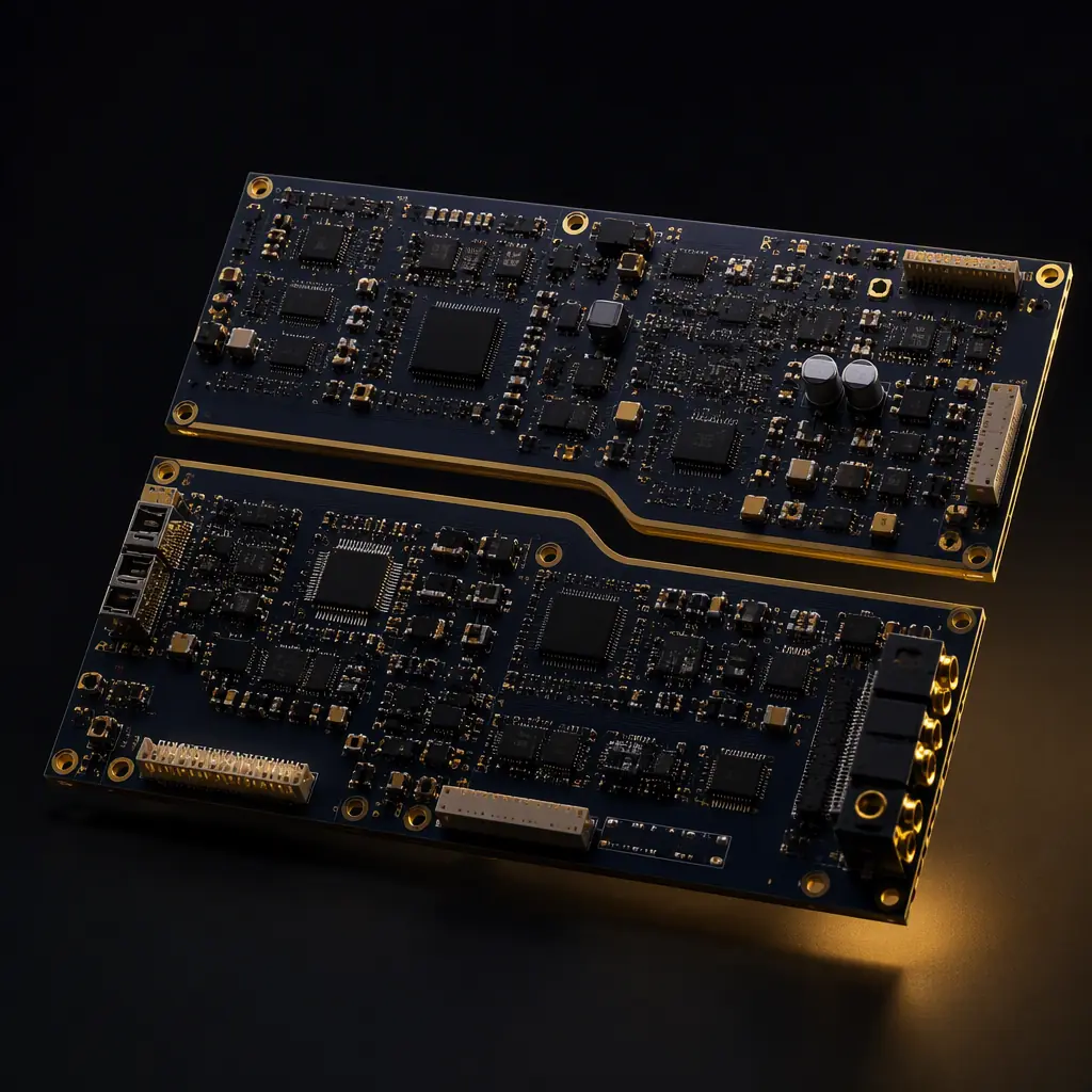
IEC 60601-1 is the safety standard every medical electrical device must pass to be sold in the EU, and it underpins certification almost everywhere else. But here is what most procurement teams discover late: compliance is decided as much on the printed circuit board as it is in the enclosure. Creepage distances that exist only in the schematic, isolation barriers that were never implemented on the layout, coatings applied to boards that were never qualified. These are the reasons devices fail dielectric strength and leakage current tests at the certification lab.
This guide translates the standard into concrete PCB and PCBA requirements: what MOPP and MOOP mean for your board design, the creepage and clearance numbers that apply at 250 V working voltage, the tests your assembled boards must pass, and the documentation you should contractually require. Huaxing PCBA manufactures and assembles medical-grade boards under ISO 13485 and IPC Class 3 processes, and our engineering team reviews isolation and safety requirements on every medical order. This is the checklist we apply before a board ships.

What IEC 60601-1 Actually Governs: MOPP, MOOP and Applied Parts
IEC 60601-1 (the current edition is 3.1, published as 60601-1:2005 + A1:2012 + A2:2020) protects the patient and the operator from electric shock. It does this through a system of "means of protection": each means is one MOPP (Means Of Patient Protection) or MOOP (Means Of Operator Protection). A typical device needs two MOPP between the patient and mains, or one MOPP plus an equally protective measure, and one MOPP between the patient and any applied part that can deliver current.
For PCB designers and buyers, the practical effect is a set of hard numbers:
Two MOPP means 4 mm creepage and 2 mm clearance at 250 V
At a working voltage of 250 V AC, one MOPP requires 2 mm creepage and 1 mm clearance on the PCB surface. Two MOPP doubles both: 4 mm creepage and 2 mm clearance. For reinforced insulation (often used instead of two MOPP), the numbers are the same 4 mm / 2 mm. These distances must be measured on the actual PCB layout. A slot or a solder mask island between the traces does not count as creepage distance unless the slot depth is designed in.
Material group CTI decides how much creepage you need
The 4 mm figure assumes material group I (CTI ≥ 600). Most standard FR-4 laminates fall into group II (CTI 400–599) or group IIIa (CTI 175–399), which pushes creepage to 5 mm or 6.3 mm for two MOPP at 250 V. If your manufacturer quotes "4 mm creepage" without asking about the laminate's CTI rating, the design may not actually comply. High-Tg FR-4 and ceramic-filled laminates commonly used in medical device PCBs often have better CTI, but the datasheet must be checked, never assumed.
Conformal coating can count as one MOPP, only if qualified
Per IEC 60601-1, a protective coating applied to the PCB can be credited as one means of protection, which lets you halve the creepage requirement to 2 mm. But the coating must be qualified under IEC 60601-1's coating test (Clause 16.4), which includes a pin-hole test and a hipot test on coated test coupons. If you are relying on conformal coating to meet isolation, the coating material, its thickness (typically 25–75 µm acrylic or 30–100 µm silicone), and the qualified process must all be documented by the assembler. A bare "we coat everything" statement is not evidence.
Applied parts are classified BF or CF, and the PCB must match
Type BF parts (surface contact with the patient) allow up to 100 µA patient leakage normal condition; Type CF parts (direct cardiac contact) are limited to 10 µA. The stricter the class, the more attention the isolation barrier needs on the PCB: guard rings around the applied-part circuitry, dedicated isolation slots, and physically separated ground planes between the patient side and the secondary side. These are layout features, not component features, they have to be on the board file.
Key Takeaway: Isolation compliance is a layout and process property. Ask your supplier for the creepage/clearance values actually implemented on the board (with CTI noted), not just a certificate that says the standard name.
PCB-Level Design Rules That Determine Compliance
Beyond creepage and clearance, several board-level decisions control whether the finished assembly passes the safety tests. These are the details our engineers check in the DFM review before production.
Isolation slots and slots-through-plating
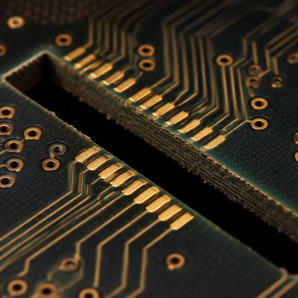
Where 4 mm creepage cannot be routed around, designers cut slots through the board. A slot must extend through the laminate and be free of plating on the wall, or the plating itself becomes a conductive path that defeats the isolation. Slot edge quality (no copper burrs, no plating wicking) is a fabrication QC point. It is verified by microsection and by visual inspection under IPC-A-600 criteria. See our guide on reading cross-section reports for what the evidence should look like.
Separation of primary, secondary and applied-part planes
The mains (primary) side, the isolated secondary side, and the patient (applied part) side must each have dedicated ground/power planes that overlap only at the isolation barrier. A single shared ground plane that sneaks under the isolation transformer's secondary winding is the single most common layout defect found in failed devices, it looks fine in the schematic and fails at the lab.
Working voltage measurement points
Creepage requirements are a function of working voltage, and the worst-case working voltage often appears across a gap you did not design for: for example, between a trace on the primary side and the mounting hole of a heatsink bracket. The design review must identify every point where primary and secondary (or patient) conductors face each other across the PCB surface, including across the board edge. This is why the DFM review should be done by a manufacturer that understands medical isolation, not a generic quoting tool.
Cleanliness and ionic contamination
Leakage current across a "clean" board can be carried by flux residue and ionic contamination. The safety standard's leakage limits assume a clean assembly; a board that fails hipot or leakage at 100 µA after a no-clean flux process often passes after proper cleaning. If your medical assembly uses no-clean flux, demand ionic cleanliness verification (ROSE per IPC-TM-650 2.3.25), our ionic contamination guide explains the test and its limits.
The Tests Your Assembled Boards Must Pass
IEC 60601-1 defines the type tests performed on the finished device, but several are directly influenced by the PCBA and are routinely repeated at board level during production. As a buyer, you should know both the device-level numbers and what the board factory can verify for you.
| Test | Typical Requirement (2 MOPP, 250 V) | Board-Level Equivalent |
|---|---|---|
| Dielectric strength (hipot) | 1500 V RMS (or 4000 V peak for reinforced), 1 minute, no breakdown | Hipot on isolation test coupons / sample boards |
| Patient leakage current | ≤ 100 µA (BF) / 10 µA (CF), normal condition | Leakage measurement on populated assemblies |
| Insulation resistance | ≥ 2 MΩ (typically ≥ 50 MΩ achieved) | 500 V DC IR test between isolated nets |
| Creepage/clearance | 4 mm / 2 mm (2 MOPP) at 250 V | Visual + microscope verification, microsection |
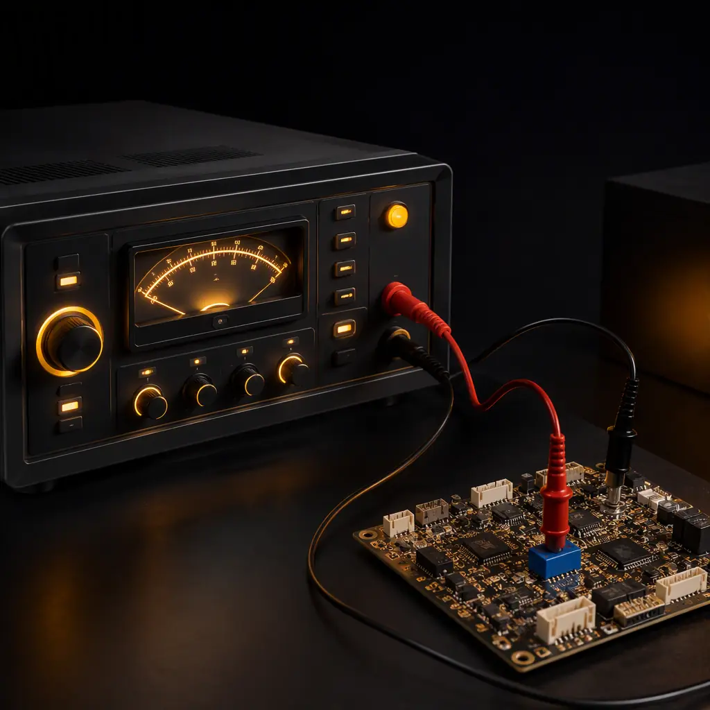
The hipot test is the one that most often fails on the bench. If the isolation transformer is fine but the board fails at 1500 V, the cause is almost always a layout or cleanliness issue: insufficient creepage on the layout, plating burrs in a slot, or ionic residue bridging the barrier. All three are manufacturing-verifiable. A qualified medical PCBA supplier will run hipot and IR tests on medical orders and provide the records, if your supplier cannot produce per-lot hipot records, treat that as a red flag.
Procurement Tip: In your RFQ, state the test voltage, duration, and acceptance criteria explicitly (e.g., "1500 V RMS, 60 s, no breakdown, between primary and secondary"). A supplier that confirms the test in writing is a supplier that has run it before.
Documentation Buyers Must Demand From the PCBA Supplier
IEC 60601-1 compliance is ultimately demonstrated by the device manufacturer's technical file, but the PCB and assembly evidence flows from your supplier. These documents should be part of the purchase agreement for any medical-grade production run:
Material certifications with CTI and flammability data
Laminate datasheets or UL yellow cards showing CTI group, UL 94 V-0 rating, and Tg. The CTI group directly affects the creepage values the design relies on. A laminate substitution (e.g., FR-4 to a lower-CTI economy grade) can silently invalidate the safety analysis. See our PCB materials guide for how laminate grades differ.
Coating qualification records
If conformal coating is part of the isolation strategy: coating material datasheet, thickness measurement records, and the pin-hole/hipot qualification results per IEC 60601-1 Clause 16.4. This is separate from a generic coating certificate, it must reference the standard's coating test.
Per-lot test records
Hipot, IR, and (where specified) leakage current records for the lot, plus AOI/X-ray and functional test reports. The electrical safety records should be traceable to the same serial numbers or lot codes that ship to you, see our traceability guide for how lot codes should map to test data.
Quality system evidence
ISO 13485 certification (not just ISO 9001) for the assembly site, IPC Class 3 acceptance criteria applied to the boards, and change-notification procedures. The wider certification picture is covered in our certifications and compliance guide.
Supplier Qualification Checklist for Medical PCBA
When you shortlist assemblers for a device governed by IEC 60601-1, verify these six points before sending files:
ISO 13485 scope covers assembly, not just fabrication
Some suppliers hold ISO 13485 for bare-board fabrication but not for SMT assembly. The scope certificate must list assembly operations. Our medical device PCB guide covers the full certification stack for medical boards.
Isolation-aware DFM review
The supplier's DFM report should check creepage/clearance against your stated working voltage and note CTI assumptions, not just minimum trace/space. This requires engineering judgment, not an automated checker.
Hipot and IR capability in-house
If the supplier outsources electrical safety testing, request the subcontractor's qualifications. In-house testing means shorter lead times and records that are easier to audit.
Coating process qualified for medical isolation
Ask which coating materials are qualified for IEC 60601-1 isolation credit, and whether they can produce the Clause 16.4 test evidence. Not all coating lines can.
Controlled material sourcing
Laminate and component substitutions must require written approval. An unauthorized FR-4 swap can change CTI, Tg, and flammability, all safety-relevant. Our counterfeit detection guide covers component provenance controls.
Cleanliness verification for no-clean processes
ROSE testing per IPC-TM-650 2.3.25 or equivalent, with limits agreed in the spec. For assemblies that will carry 100 µA leakage limits, cleanliness is a compliance variable, not a cosmetic one.
Summary: What to Take to Your Next Medical RFQ
IEC 60601-1 compliance is not a single certificate. It is a chain of layout decisions, material choices, process controls, and test records. As a buyer, you control the strongest links: specifying creepage/clearance with CTI in mind, demanding hipot and IR test evidence per lot, and qualifying suppliers that can actually produce the documentation. When in doubt, a first article inspection with cross-sections and hipot on the first production lot is the cheapest insurance against a lab failure six months later.
At Huaxing PCBA, we manufacture and assemble medical PCBs under ISO 13485 and IPC Class 3 processes, with in-house AOI, X-ray, ICT, functional test, and hipot/IR capability. Our DFM review checks isolation requirements against your working voltage before production starts. Contact our engineering team with your Gerber files and target standard. We will confirm the isolation layout and test plan within 24 hours.
