

There is a reflex in electronics assembly that reaches for full underfill whenever a BGA or chip-scale package appears on a board. It is a safe reflex, and on high-reliability programmes it is the correct one. But full underfill is also the most expensive, slowest and least reworkable of the three package reinforcement methods available, and on a large share of commercial boards it is more protection than the design needs. Corner bonding and edge bonding exist precisely to fill that space.
The distinction is mechanical. Full underfill couples the entire package footprint to the board, so it reduces strain in every joint across the array. Corner bonding and edge bonding anchor the package only at selected points, so they reduce the displacement at those points and — through the stiffness of the package substrate itself — reduce the relative motion of the whole array. The result is a meaningful but smaller improvement in joint fatigue life, delivered in a fraction of the process time.
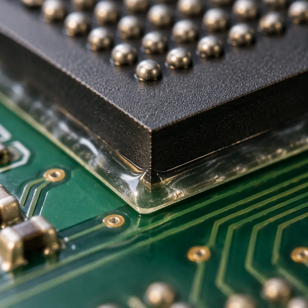
The Three Methods Compared
Before the selection rules, the raw comparison. The numbers below are typical of a 15 mm BGA on 1.6 mm FR-4 with 0.8 mm pitch, which is a common reference geometry for this decision.
| Parameter | Corner Bond | Edge Bond | Full Underfill |
|---|---|---|---|
| Material volume per package | 2–4 mg | 10–25 mg | 80–250 mg |
| Application time | 3–6 s | 10–20 s | 45–120 s |
| Cure | Inline, 3–5 min at 130 °C | Inline, 3–5 min at 130 °C | Batch, 30–60 min at 150 °C |
| Fatigue life improvement | 1.5–2.5× | 2–5× | 5–15× |
| Drop-test improvement | Moderate | Strong | Strongest |
| Rework feasibility | Good | Moderate | Very low |
| Needs paste compatibility testing | No | No | Yes (no-flow) |
| Relative process cost | 1× | 2–3× | 8–15× |
The fatigue-life multipliers are approximate by nature — they depend heavily on package size, standoff, board thickness and the thermal cycle range — but the shape of the trade is stable across designs. Corner bonding buys a moderate improvement for almost no process cost. Edge bonding buys roughly double that for two to three times the cost. Full underfill buys the rest, at eight to fifteen times the cost of corner bonding.
Key Takeaway: The right question is not "should we underfill?" but "how much fatigue life does this design actually need?" Full underfill is the correct answer to a smaller set of designs than its usage rate suggests.
When Corner Bonding Is Enough
Corner bonding places a small dot of high-modulus adhesive at each of the four corners of the package, bridging from the package edge down to the board. It is applied after reflow, cures in minutes at relatively low temperature, and is compatible with a wide range of board finishes because it never touches the solder joints themselves.
The mechanism is a reduction in package-edge displacement. In a cycled assembly, the corners of a large package experience the largest relative motion between package and board. Anchoring those four points reduces the amplitude of motion across the whole array, because the package substrate transmits the constraint inward. The corner joints — which are the first to fail in an un-reinforced assembly — are exactly the ones that benefit most.
Commercial Products With Moderate Thermal Excursion
If the operating range is roughly 0 °C to +70 °C and the product is not exposed to repeated thermal shock, corner bonding alone frequently satisfies the qualification. Consumer, office and general industrial electronics fall into this band. Where the range widens to −40 °C to +125 °C, the calculus changes and edge or full underfill becomes the safer default.
Larger Packages With Low to Moderate Standoff
Corner bonding works best where the package substrate is stiff enough to transmit the constraint. Large body packages with a relatively thick substrate respond well. Very thin packages and fine-pitch chip-scale devices with tiny standoffs gain less, because the substrate is too compliant to distribute the anchoring effect — those are candidates for full underfill instead.
Programmes Where Rework Must Remain Possible
Corner-bonded packages can still be removed. The adhesive at the corners is mechanically broken and cleaned, and the usual rework and repair process applies with only a modest increase in care. On a programme where engineering change activity is likely, or where field returns need to be analysed by removing the package, that flexibility has real value that never appears in a cost comparison.
Cost-Sensitive Builds With Hundreds of Packages
On a board carrying twenty or more large packages, applying full underfill to all of them is often impractical in both process time and floor space. Corner bonding scales, because it adds only seconds per package and cures inline. The practical approach on dense boards is tiered protection — full underfill on the two or three highest-risk devices and corner bonding on the remainder. Our BGA assembly guide covers how packages are prioritised by risk.
When You Need Edge Bonding
Edge bonding applies adhesive along two opposite sides or around the full perimeter of the package, forming a continuous bead from package edge to board. It sits between corner bonding and full underfill in both performance and cost, and it is the right answer more often than either of the extremes.
The reason edge bonding is a good default for portable electronics is that it addresses the dominant failure mode in that segment — drop and mechanical shock — more efficiently than full underfill does per unit of process cost. Under drop loading, the board flexes and the package tries to peel away from it. A perimeter bead directly resists that peeling. Full underfill also resists it, but it does so by coupling every joint, which is more than drop performance alone requires.
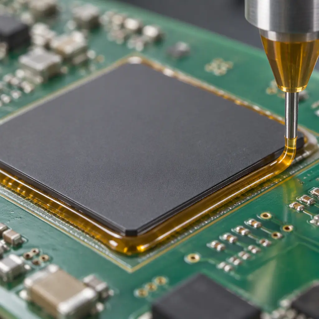
Portable and Handheld Products With a Drop Requirement
A product with a defined drop test — typically 1.0 to 1.5 m onto concrete, six faces — is the classic edge bonding application. The perimeter bead absorbs and distributes the peel loading that would otherwise concentrate on the outermost joints. Handheld instruments, portable medical devices and industrial handheld terminals all fit this profile.
Mixed Thermal and Mechanical Loading
Products that see both temperature cycling and vibration — automotive under-hood modules, outdoor equipment, transport-mounted electronics — benefit from edge bonding's dual action. It reduces the displacement that drives thermal fatigue while simultaneously resisting peel loading from vibration. Our vibration and shock testing guide covers how those requirements are specified and verified.
Where Thermal Cycling Is Real but Not Extreme
A range of −40 °C to +105 °C, typical of many automotive and outdoor applications, sits in the zone where edge bonding is often sufficient. Extending to +125 °C and above is where full underfill earns its cost. The transition is not a sharp line, so the honest approach is to qualify the specific design against the specific cycle rather than to reason from a rule of thumb.
Packages Where Full Fill Cannot Be Verified
On a package with a very fine gap or a densely populated underside, achieving and verifying complete capillary fill is genuinely difficult — acoustic scanning may not resolve voids reliably, and incomplete fill is worse than no fill. Edge bonding sidesteps the verification problem entirely, because the bond is fully visible and its geometry is measurable optically. Our cross-section and microsection guide covers the verification methods available when destructive analysis is needed.
When Only Full Underfill Will Do
Full underfill remains the correct choice for a well-defined set of designs. The pattern across all of them is that the thermal or reliability requirement is severe enough that the margins are thin, and there is no room for an approximate solution.
Automotive Under-Hood and Safety-Critical Electronics
Requirements of 2,000+ thermal cycles from −40 °C to +125 °C, combined with IATF 16949 process control and functional safety requirements, leave no margin for partial reinforcement. Full underfill is the default. Our ISO 26262 functional safety guide covers how the reliability case is constructed for those programmes.
Fine-Pitch Chip-Scale Packages
Below roughly 0.5 mm pitch, the joints are small enough and the standoff low enough that corner and edge bonding cannot develop sufficient constraint to matter. The joint-level strain remains high regardless of edge anchoring. This is the clearest case where the process cost of full underfill is simply the price of a working design — the mechanism is covered in our CSP underfill process guide.
Medical Implantable and Mission-Critical Devices
Where a field failure carries a clinical or mission consequence, the reliability margin has to be beyond argument rather than merely adequate. Full underfill, combined with the appropriate encapsulation and inspection regime, is standard for implantable and life-support electronics. Our implantable medical device guide covers the wider requirements.
Aerospace, Defence and Space
Extreme temperature ranges, high vibration and long service life without maintenance access push these programmes to full underfill as a matter of course. Our aerospace and defence PCB guide and LEO satellite applications guide cover the thermal cycling and outgassing requirements that drive the decision.
Rework, Testability and the Cost Nobody Plans For
The application cost of these three methods appears in the quote. The consequences do not, and they are frequently larger. A full underfill decision made to gain fatigue life can quietly eliminate the ability to rework a package, which turns every subsequent engineering change into a board respin.
Underfill also interacts with test. A fully underfilled package is difficult to probe, and if the process requires bonded joints to be reinforced before test, then a package that fails test is a scrap decision rather than a rework decision. Sequencing matters: reinforce after functional test wherever the process allows, which is another argument in favour of corner and edge bonding — both are post-reflow, post-test operations, while no-flow underfill necessarily comes before reflow and therefore before test.
Procurement tip: When comparing quotes from two assemblers on the same board, check whether they specified the same reinforcement method. A quote built on corner bonding and a quote built on full underfill can differ substantially in price and look like a like-for-like comparison. Ask each supplier to state the method, its application time and its cure schedule explicitly.
A Practical Selection Sequence
The decision reduces to four questions, answered in order. In most programmes the first two settle it.
What Is the Qualification Test?
Name the actual test: cycle count, temperature range, drop height, vibration profile. If the requirement is 2,000 cycles from −40 °C to +125 °C, go to full underfill. If it is 500 cycles from 0 °C to +70 °C, corner bonding is very likely sufficient. This one answer eliminates most of the decision space.
What Is the Package Pitch and Standoff?
Below 0.5 mm pitch, full underfill. Between 0.5 mm and 1.0 mm, edge bonding is usually the sensible middle. Above 1.0 mm with a stiff substrate, corner bonding is worth qualifying. The smaller the joint and the lower the standoff, the less a partial reinforcement can help.
Does Rework or Engineering Change Need to Remain Possible?
If the answer is yes, that is a strong argument against full underfill and in favour of corner or edge bonding — unless question 1 already forced the full-fill answer, in which case the rework constraint has to be accepted and planned for. Our engineering change order guide covers how to manage the process when rework is not available.
How Many Packages on the Board?
One or two high-risk devices justify full underfill individually. Twenty-plus packages usually call for a tiered approach — full fill on the critical few, edge or corner bonding on the rest. Treating all packages identically is rarely the cost-effective answer on a dense board. See our design for assembly guide for how reinforcement decisions fit into the wider assembly review.
Getting the Decision Right the First Time
At Huaxing PCBA we run corner bonding, edge bonding, capillary underfill and no-flow underfill in the same house as our surface-mount and through-hole assembly, so the recommendation is driven by the qualification test rather than by which process we happen to own. Every reinforcement decision we quote comes with the method named explicitly, along with its application time and cure schedule — so a price comparison between suppliers stays a like-for-like comparison. Our builds carry AOI, X-ray and SPI inspection and first article inspection with dimensional reporting as standard. Send your Gerber, BOM and qualification requirement and we will tell you which of the three methods your design actually justifies.
