
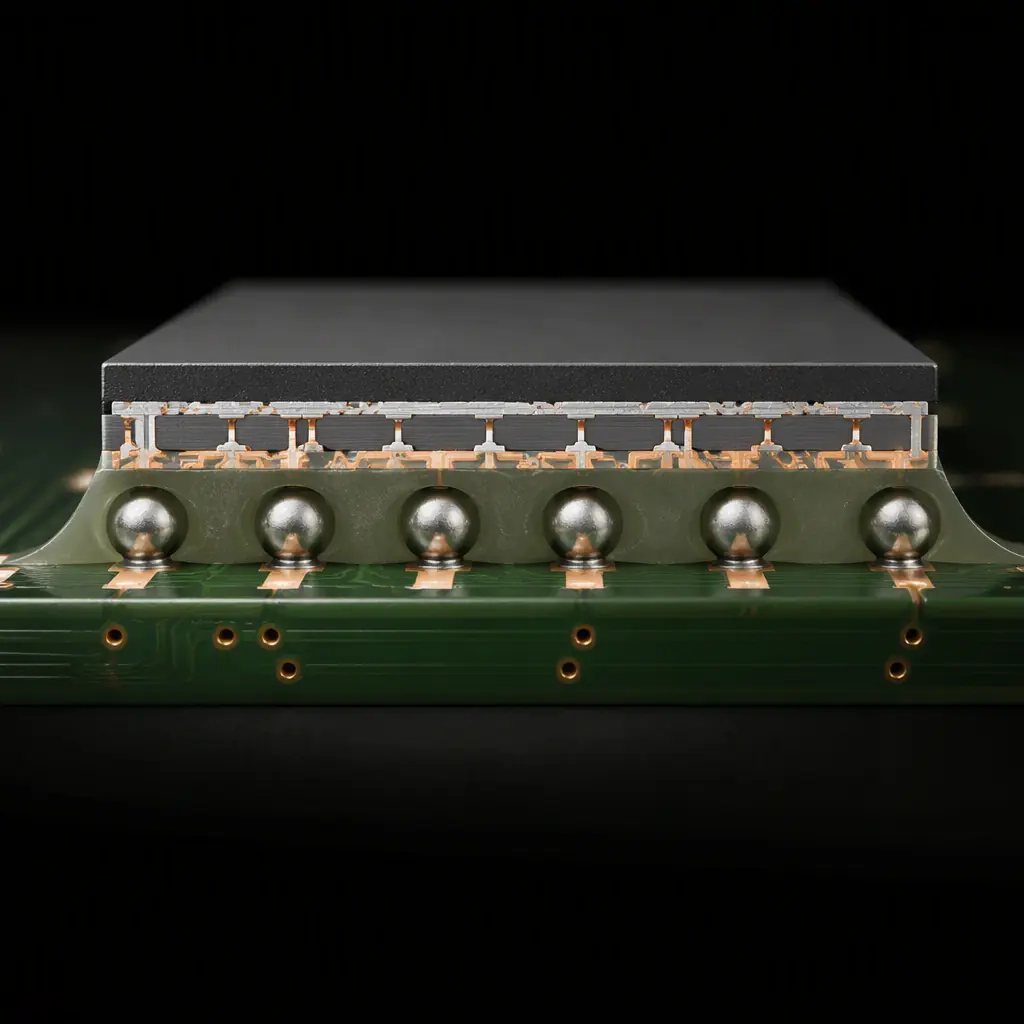
Underfill is a polymer material applied between an area-array package (BGA, CSP, flip-chip) and the PCB, filling the gap around the solder balls. It does one job better than anything else: it distributes the mechanical stress caused by thermal expansion mismatch between the silicon die and the board, so the solder joints don't crack over thousands of temperature cycles.
The reliability stakes are real. A bare BGA under continuous thermal cycling can fail in 2,000–5,000 cycles depending on ball pitch, die size and board material. The same package with proper underfill routinely exceeds 10,000 cycles. For automotive, aerospace, medical and industrial boards, where field failure means recall or downtime, underfill is often a specification requirement, not an option.
When Does a Board Actually Need Underfill?
Underfill adds cost, cycle time and process complexity. So the first question is always whether it's required. The decision drivers:
Thermal cycling environment
Automotive underhood, aerospace, outdoor industrial, wide temperature swings accelerate solder fatigue. If your board lives in an environment with more than ~40°C of temperature excursion, underfill is worth evaluating seriously.
Large die-to-board expansion mismatch
Large BGAs and flip-chips (die size above ~10 mm) with standard FR-4 boards generate the most stress. Smaller packages and low-CTE boards (like our high-performance laminates) tolerate more cycling without underfill.
Mechanical shock and vibration
Handheld, portable and mobile products subject BGAs to drop and vibration loads. Underfill is the standard solution in wearables and mobile electronics, our vibration testing guide covers the qualification side.
Industry requirements
Aerospace, defense and automotive specifications frequently mandate underfill for area-array packages. If your product follows MIL or AS9100 requirements, check the package-level requirements early.
Key Takeaway: If any of these four conditions apply to your BGA or flip-chip board, underfill should be in the design conversation, before layout freezes, not after the first field failure.
Capillary Underfill: The Workhorse Process
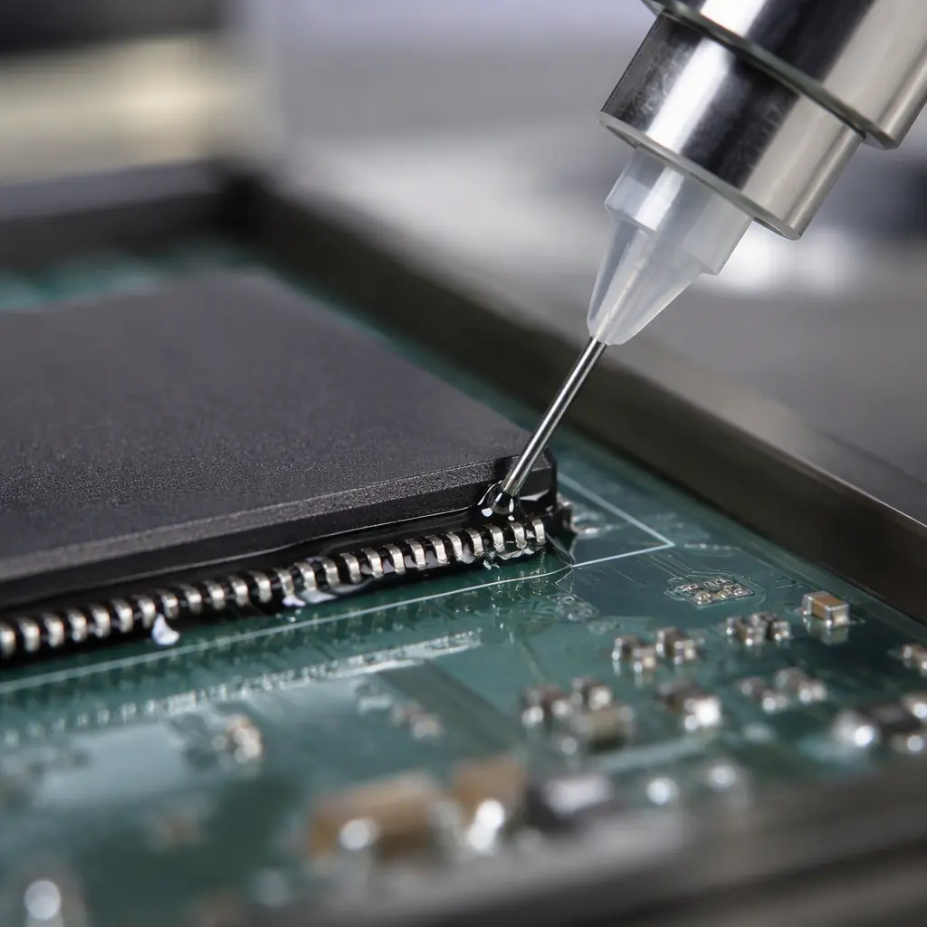
Capillary underfill is the classic method: after reflow and inspection, a needle dispenses a line of low-viscosity epoxy along one or two edges of the package. Capillary action pulls the material under the chip, filling the gap between the solder balls. The board then goes through an oven to cure the epoxy.
Why it dominates high-reliability applications:
Complete gap filling
Capillary flow fills the entire gap under the die, including under the solder balls, giving the best mechanical support. This is why it's preferred for large dies and the most demanding environments.
Wide material selection
Capillary underfills come in standard, low-CTE, fast-cure and reworkable formulations, so the material can be matched to the actual stress environment.
Proven reliability data
The thermal cycling performance of capillary underfill is documented across decades of automotive and aerospace qualification. When a customer asks for "the same reliability as the last program," capillary is usually the answer.
The cost side: capillary underfill requires a dedicated dispense step plus a cure oven, adding roughly 30–90 minutes of process time per batch depending on material. It also makes rework difficult, the package is bonded to the board. Our BGA assembly guide covers the reflow and inspection side of BGA processing.
No-Flow Underfill: Process and Trade-Offs
No-flow underfill combines flux and underfill in one material. The paste is dispensed on the board before component placement, the BGA is placed into it, and the reflow profile cures the material in the same pass, no separate dispense-and-cure step.
The advantages are process simplicity and speed. The trade-offs matter:
Faster cycle time
No separate underfill dispense and cure steps, the reflow oven does both. For high-volume consumer products this is a significant cost saver.
Higher void risk
No-flow materials trap more voids than capillary flow, especially under large dies. Voids act as stress concentrators, partially defeating underfill's purpose. Void control requires careful reflow profiling.
Limited rework window
If placement is wrong, the no-flow material is already there. Rework requires cleaning the uncured material, which is messy and sometimes impossible on fine-pitch parts.
Best for small to medium packages
No-flow is a pragmatic choice for CSPs and moderate BGAs in consumer and handheld products. For large dies in harsh environments, capillary remains the safer call.
Molded Underfill and Edge-Bond: The Alternatives
Two other approaches are worth knowing when you see them in specs:
Molded underfill (MUF)
Used mainly in fan-out wafer-level packaging (FOWLP) and some flip-chip BGA production, where the underfill is applied as part of the mold process. It's a packaging-level technology rather than an assembly-level one, if your supplier quotes MUF, it happens at the package house, not the board house.
Edge-bond / corner-bond adhesives
Instead of filling the entire gap, edge-bond places small adhesive dots at package corners or edges. It provides much less stress relief than full underfill but is dramatically cheaper and reworkable. It's a middle ground for boards with moderate shock requirements and small packages. Our flip-chip and IC packaging guide discusses package-level variants in depth.

Capillary vs No-Flow: The Selection Table
| Criteria | Capillary Underfill | No-Flow Underfill |
|---|---|---|
| Process steps | Dispense after reflow + separate cure | Dispense before placement, cured in reflow |
| Cycle time | Longer (extra steps) | Shorter |
| Gap filling completeness | Full, best support | Good, but void risk higher |
| Large die support | Excellent | Marginal (void control) |
| Reworkability | Difficult, sometimes impossible | Difficult (material present pre-reflow) |
| Cost per board | Higher (material + process) | Lower at volume |
| Typical applications | Automotive, aerospace, medical, industrial | Consumer, handheld, cost-sensitive |
The selection isn't just about cost, it's about matching the material's stress-relief capability to the actual thermal and mechanical environment. A consumer wearable and an automotive ECU both use BGAs, but they need different underfill strategies.
Design Rules That Make Underfill Work
Underfill can't fix a layout that fights it. Four design rules keep the process reliable:
Keep the gap clear under the package
No solder mask, no silkscreen, no vias with unfilled holes under the BGA body. Unfilled vias act as "solder thieves" and block capillary flow. Via-in-pad designs need plugged or filled vias, see our via fill types guide.
Design the dispense pattern
An L-shape or line along one edge is standard for capillary underfill; the pattern should follow the package edge with a small offset. For no-flow, the dispense dot pattern must cover the ball array footprint without excess material that bleeds out.
Consider the cure oven footprint
If capillary underfill is chosen, the board must fit the cure oven and the material's cure schedule must be compatible with the BOM's temperature sensitivity. High-temperature cure materials (150°C+) can damage low-temperature components.
Leave room for inspection
Keep package edges visible for visual and AOI inspection of the fillet (the visible underfill bead around the package). A fillet that's too small or missing signals incomplete fill.
Void Control and Inspection
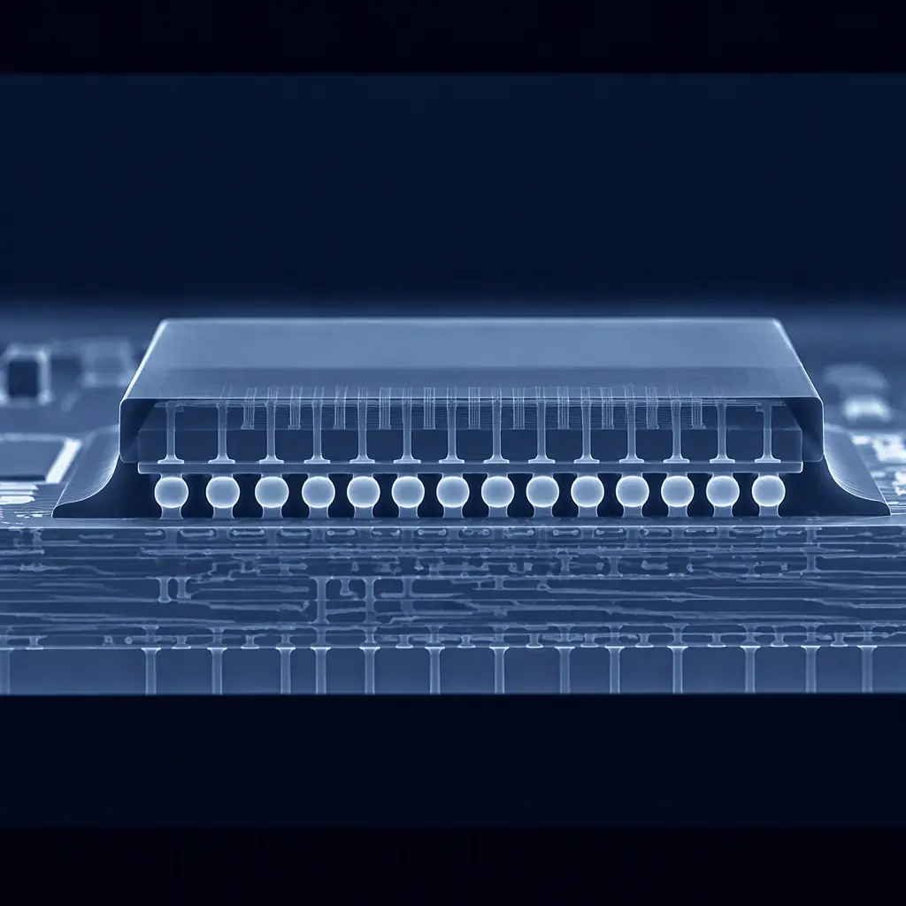
Voids are underfill's main quality enemy. A large void under the die center leaves the solder joints there unprotected, recreating the exact stress concentration underfill is meant to eliminate. Inspection methods:
Visual and AOI fillet inspection
First-line check: consistent fillet height and coverage around all four package edges. Missing fillet on one side = incomplete flow.
X-ray for void detection
Underfill material absorbs X-rays differently than solder, so voids show up in X-ray as lighter regions in the package shadow. This is the standard production verification for void content. Our inspection methods guide covers X-ray technique.
CSAM for development
Scanning acoustic microscopy (C-SAM) is the gold standard for detecting delamination, the interface separation between underfill and die or board. It's slower and more expensive, so it's used for qualification and failure analysis rather than 100% production inspection. See our failure analysis guide for when it's called for.
Qualification: What to Demand in Testing
If underfill is a reliability feature, it needs reliability evidence. The qualification tests that matter:
| Test | Standard | What It Verifies |
|---|---|---|
| Thermal cycling | JESD22-A104 / IPC-9701 | Solder joint survival under temperature excursions, the core underfill benefit |
| Drop / shock | JESD22-B111 | Mechanical robustness for handheld and portable products |
| Vibration | JESD22-B103 | Endurance under sustained vibration, see our vibration testing guide |
| Moisture resistance | JESD22-A101 / IPC/JEDEC J-STD-020 | Underfill adhesion and package integrity under humidity |
Ask your CM or material supplier for these test results before freezing the material choice. A material that passes thermal cycling but fails drop testing will fail in the field for exactly the product category that needs underfill.
Procurement Tip: When underfill is on the BOM, specify the material by manufacturer part number (e.g., Namics, Henkel, Loctite, Panasonic formulations) and demand the qualification data. "Underfill" alone on a BOM leaves the CM free to substitute a material that may not match your reliability requirements.
Cost and Lead Time Reality
Underfill adds real cost. Budget expectations:
Material cost
Underfill material typically adds a few dollars per large BGA, less for small packages. It's a small fraction of board cost but not free.
Process cost
Capillary underfill adds a dispense pass and a cure cycle, call it 10–20% extra assembly time for the boards that carry it. No-flow is cheaper per board but has higher void risk.
Rework cost
The hidden line item. Underfilled packages are effectively non-reworkable. A failed underfilled BGA means scrapping or expensive removal with solvent. Design for it: place underfilled packages where a board-level sacrifice is least painful. Our rework guide covers BGA reballing for the non-underfilled cases.
The Bottom Line
Underfill is one of the highest-leverage reliability decisions on a board with area-array packages. Capillary underfill buys the most protection for harsh environments; no-flow buys process speed for cost-sensitive products; edge-bond is a pragmatic middle ground. The material, the process and the inspection must be specified together, and verified with real test data.
At Huaxing PCBA, we run capillary and no-flow underfill across our 8 SMT lines, with X-ray void inspection and access to qualified materials from the major suppliers. Send us your Gerbers and BOM for a free DFM review and 24-hour quote . We'll flag whether your area-array packages need underfill, and spec the right material and process for your reliability target.
