

A chip-scale package (CSP) is a mechanical compromise. The package is barely larger than the die inside it, so there is almost no compliant material between the silicon and the board to absorb the difference in thermal expansion. Silicon expands at roughly 2.6 ppm/°C; a standard FR-4 board expands at 14–17 ppm/°C in-plane. On a 10 mm package, a 100 °C excursion from reflow to cold soak produces a shear displacement at the outermost solder joint that the joint alone cannot absorb indefinitely. Underfill exists to move that stress off the solder joint and into a filled epoxy that spreads it across the whole package footprint.
The failure it prevents is not instant — it is a fatigue failure that shows up as an open circuit in the field after 500 to 2,000 thermal cycles, which is exactly the kind of defect that turns into a warranty claim instead of a rework ticket. Our underfill work runs on the same lines that place 0201 components and 0.3 mm pitch BGA at Huaxing PCBA, which matters because the process window for underfill is set by the same placement accuracy that governs the joints it is protecting.
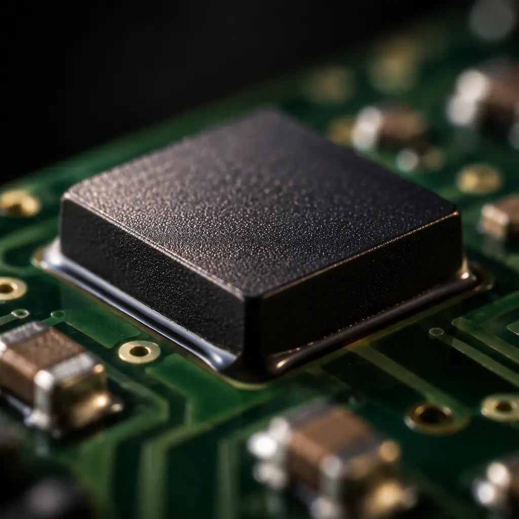
Why CSPs Fail Without Underfill
The solder joint in a CSP is a small ball — typically 0.2 to 0.5 mm diameter — with a low standoff. Low standoff means the joint has very little length over which to distribute strain. Strain in a solder joint scales with the displacement divided by the joint height; halve the standoff and you double the strain for the same displacement. That is the entire mechanical argument for underfill in one sentence.
There are three distinct failure modes that underfill addresses, and it is worth knowing which one applies to your design because they drive different process requirements.
Thermal Fatigue Cracking at the Joint
Repeated cycling cracks the solder at the intermetallic boundary, usually on the package side. Underfill redistributes this by mechanically coupling the package to the board, reducing the strain amplitude in the joint itself. For a 0.4 mm pitch CSP on FR-4, un-filled assemblies commonly fail between 700 and 1,200 cycles from −40 °C to +125 °C; the same assembly with a correctly applied capillary underfill typically exceeds the 2,000-cycle test duration. Our thermal cycling test guide covers how that qualification is actually run and what a valid comparison requires.
Mechanical Shock and Drop Damage
In handheld and portable products, drop loading puts a transient bending moment into the board. Without underfill, the outermost joints take almost all of it. This is the failure mode that dominates consumer wearables and handheld instruments, and it is the reason underfill requirements in those products are driven by drop test rather than thermal cycling.
Moisture and Ionic Ingress
A CSP with a 0.15 mm gap between package and board is a capillary channel. Flux residue trapped in that gap becomes a conductive path once humidity condenses. Underfill displaces the air in that gap with a dielectric, which is why cleanliness before dispense matters more than most process engineers expect — the underfill is only as reliable as the surface it bonds to. Our ionic contamination testing guide explains how that residue is quantified before encapsulation.
Key Takeaway: Underfill is a fatigue-life decision, not a cosmetic fill. If your qualification plan does not name a thermal cycle count and a drop height, you have not specified underfill — you have only specified that something should be dispensed.
Capillary vs No-Flow vs Molded Underfill
Three processes dominate, and they are not interchangeable. The choice is driven by package pitch, board density, throughput requirement, and whether the assembly can tolerate a second thermal excursion.
| Parameter | Capillary (CUF) | No-Flow (NUF) | Molded (MUF) |
|---|---|---|---|
| Process order | Reflow, clean, then dispense and cure | Dispense, then reflow and cure in one pass | Reflow, then compression molding |
| Typical cure | 30–60 min at 150 °C | In-reflow, plus 30 min post-cure | Mold compound cure, 2–4 h |
| Fillet on all sides | Yes, visible fillet | Partial, depends on dispense pattern | Fully encapsulated |
| Void sensitivity | Low to moderate | High | Low |
| Throughput impact | Adds a dispense and cure station | Minimal, folds into reflow | Requires dedicated mold tooling |
| Best fit | High-reliability, tight pitch, low volume | High-volume portable electronics | Fan-out and multi-die modules |
The throughput versus reliability trade is the real decision. Capillary underfill gives the most predictable result and the widest process window, but it adds a separate dispense pass and a 30–60 minute cure, which is why it is standard in automotive, medical and aerospace builds where volume is moderate and the qualification bar is high. No-flow underfill folds into reflow, which is why it dominates high-volume consumer work — at the cost of a much narrower window and much higher void sensitivity.
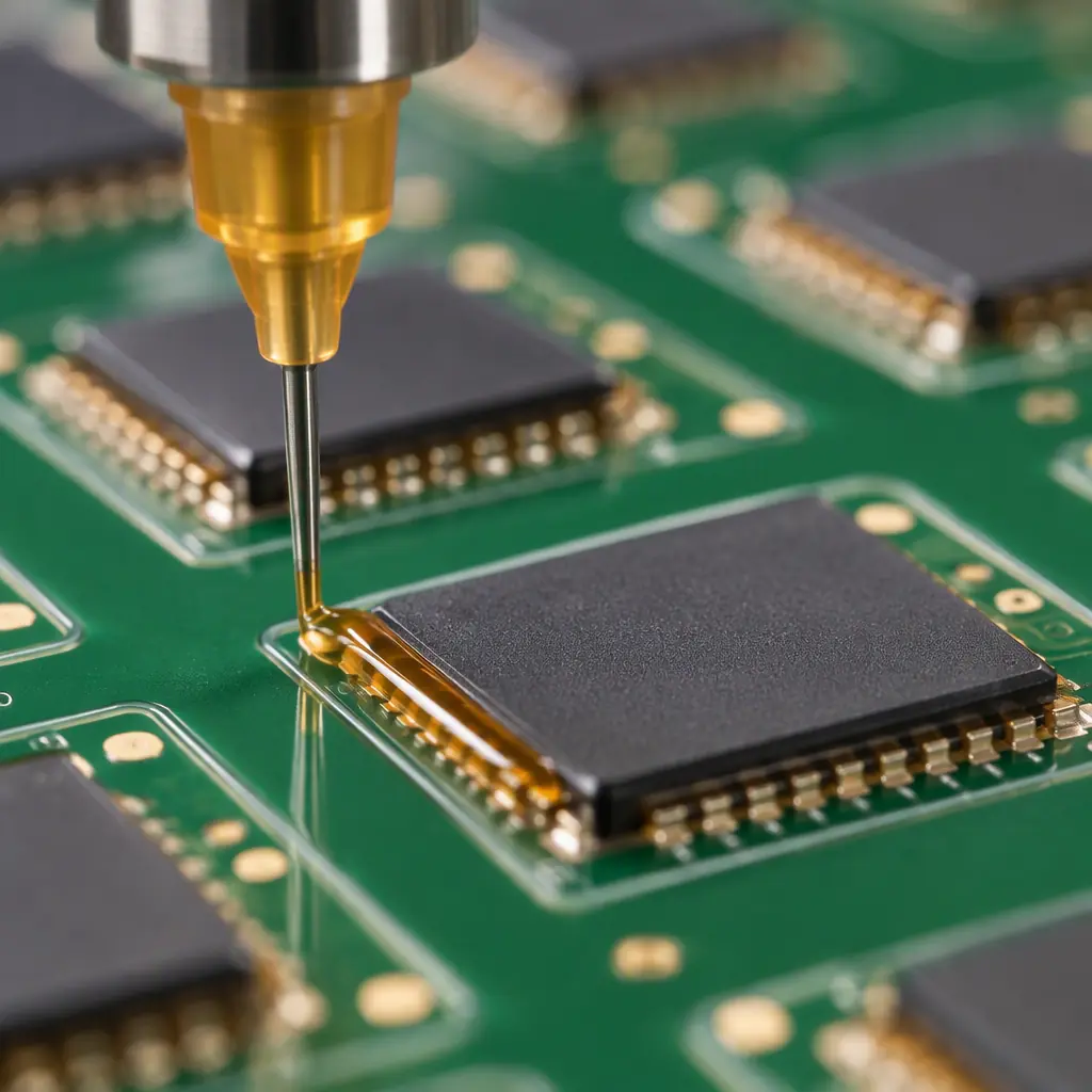
The Dispense Pattern Determines Whether It Works
Most underfill failures that get blamed on material are actually dispense geometry failures. Capillary flow is driven by the balance between surface tension pulling the liquid into the gap and viscous drag resisting it. Get the pattern wrong and you get incomplete fill, which is worse than no underfill at all because the filled region now constrains the package asymmetrically and concentrates stress on the joints that were left unfilled.
Use L-Shaped or U-Shaped Dispense for Square Packages
A single-line dispense along one edge of a square package produces a fill front that reaches the far corner last, and often reach it after the material has begun to gel. Two adjacent edges (L-shape) or three edges (U-shape) shortens the maximum flow path and gives a more even front. The rule of thumb is that the longest flow path should not exceed about 10 mm for a typical filled epoxy at 25–30 °C.
Control Substrate Temperature, Not Just Needle Temperature
Underfill viscosity is strongly temperature-dependent — a typical filled epoxy drops from roughly 12,000 mPa·s at 25 °C to under 1,000 mPa·s at 70 °C. Heating the board to 60–70 °C during dispense dramatically improves flow and reduces voids, but it also reduces the working time before gelation. Heated dispense stages with a 60–90 second window are standard for high-reliability builds.
Size the Needle to the Fillet, Not to the Package
Needle gauge controls both flow rate and placement precision. A 25–27 gauge needle is typical for CSP work; finer needles slow the dispense and risk clogging on filled materials, which are abrasive. Filled underfills wear needles, so needle replacement intervals belong in the process spec, not in a maintenance log nobody reads.
Target a Fillet, Not a Puddle
The correct visible result is a concave fillet running 0.5 to 1.0 mm up the side of the package on every edge. A puddle that spreads beyond the package onto adjacent pads risks wicking under nearby components; a fillet that does not fully wet an edge indicates incomplete fill. Both are rejectable under IPC-A-610 visual criteria.
Void Control and What the Limits Actually Are
Voids are the most common underfill defect and the most commonly misunderstood specification. A void is a bubble of air or volatilised material trapped in the encapsulant. Voids are not automatically a defect — a small, isolated, spherical void in the bulk of the fillet has minimal effect on fatigue life. Voids become a defect when they sit directly under the package in the joint field, where they interrupt the load path the underfill was added to create.
Industry practice, based on IPC/JEDEC J-STD-035 acoustic microscopy methodology, is to reject voids larger than 10% of the projected area of any single joint, and to reject any continuous void path that bridges two or more adjacent joints. Acoustic scanning (C-SAM) is the only practical way to see these, which is why underfill qualification almost always includes a scanning acoustic microscopy step rather than relying on cross-sectioning a handful of samples. Our cross-section report guide covers the destructive side of that verification and why the two methods are complementary rather than redundant.
Void formation has three dominant causes, in order of frequency:
Entrapped Air From the Dispense Pattern
If the fill front closes on itself from two directions, the last point to fill becomes a trapped bubble. This is why symmetric two-sided dispense on a large package is avoided. It is a pattern problem, fixed by changing geometry rather than material.
Moisture From an Insufficiently Baked Board
FR-4 absorbs moisture, and a board that has been out of a dry pack or sitting on a humid production floor will outgas during underfill cure. A 2 to 4 hour bake at 120 °C before dispense is standard, and it is the single most commonly skipped step in an underfill process. The same moisture-control discipline that governs components applies to the bare board — see our MSL and moisture sensitivity guide for the storage side.
Volatiles From Inadequately Cleaned Flux Residue
Flux residue under a package is a volatile source during cure. For capillary underfill, cleaning before dispense is mandatory if any-clean or water-soluble flux was used. No-clean flux processes require a compatibility check between the residue and the underfill chemistry, because some residue systems prevent the underfill from wetting the board.
Procurement tip: Ask your assembler for a C-SAM image set, not a written statement that "underfill is void-free." A scanning acoustic micrograph of an actual production sample takes minutes to produce at the bench and is the difference between a verified process and an optimistic one.
Cure Schedules and the Cost of Getting Them Wrong
Underfill cure is a two-stage process in most materials: a gel point that locks the geometry and a final cure that develops full mechanical properties. The gel point is what matters for the fillet shape; the final cure is what matters for fatigue life. An underfilled package that is handled immediately after gel but before full cure can have its fillet disturbed, and disturbed geometry is not repairable.
| Stage | Typical Schedule | What It Controls |
|---|---|---|
| Gel | 5–15 min at 100–120 °C | Fillet shape retention, flow stop |
| Full cure | 30–60 min at 150 °C | Modulus, CTE, final Tg |
| Post-cure (optional) | 60 min at 165 °C | Maximum Tg, lowest moisture uptake |
The cost consideration is that underfill cure is a batch oven operation, not an inline one, so it introduces a queue. For a build with a 7–10 day PCBA lead time this is absorbed without notice. For an expedited build it can become the critical path, which is a reason to confirm the cure schedule early rather than at the end of the programme.
Selecting a CSP Underfill: A Practical Sequence
The selection process is more constrained than the datasheet suggests, because several properties trade directly against each other. High filler loading gives low CTE and good fatigue performance but raises viscosity and slows capillary flow. Low viscosity flows well but shrinks more and has a higher CTE. There is no material that wins on all axes.
Start From the Qualification Test, Not the Material
If the product must pass 2,000 thermal cycles from −40 °C to +125 °C, that requirement eliminates most low-viscosity no-flow materials up front. If the product must survive a 1.5 m drop test, the filler content matters more than the CTE. Define the test first and the material shortlist becomes short.
Match CTE to the Joint, Not to the Silicon
A common specification error is demanding an underfill CTE close to silicon (about 3 ppm/°C). That is not achievable in a flowable filled epoxy and not necessary. What matters is that the underfill CTE sits below the board CTE and close enough to the joint that the mismatch is distributed rather than concentrated. Typical filled underfills run 20–35 ppm/°C below Tg, which is above silicon and below FR-4 by design.
Confirm Rework Strategy Before Committing
Capillary underfill makes rework of the encapsulated package practically impossible — the standard method is localised heating with a bottom-side preheater and package removal, followed by full site clean-up, and success rates fall sharply on packages below 0.5 mm pitch. If field rework or engineering change activity is expected, that constraint may justify no-flow or a reworkable underfill chemistry even at a reliability cost. Our rework and repair guide covers what is recoverable and at what risk.
Verify Flow Compatibility With Adjacent Components
Underfill does not know where it is supposed to stop. It will wick under adjacent 0201 passives, into connector housings and onto test pads if the dispense volume allows. Board-level layout should include keep-out zones and, where necessary, a dispense dam. This is one of the checks that belongs in a design-for-assembly review — see our DFA guide for the wider checklist.
How Underfill Fits Into Your Build
Underfill is usually specified late, after the package selection is locked and the board is already laid out. That ordering causes most of the problems in this article, because dispense geometry and keep-out zones are layout decisions. Bringing the underfill process into the conversation at the DFM stage costs nothing and routinely saves a respin.
At Huaxing PCBA, we run capillary underfill dispense with heated stages, acoustic microscopy verification and a full range of thermoset encapsulants alongside our surface-mount and through-hole assembly. Our process control includes AOI, X-ray and SPI inspection on every build, first article inspection with dimensional and cross-section reporting per FAI requirements, and finish options from ENIG to hard gold to match the joint metallurgy you need. Send your Gerber and BOM and we will return a DFM report that flags underfill keep-outs, dispense access and cure scheduling before the board is cut.
