
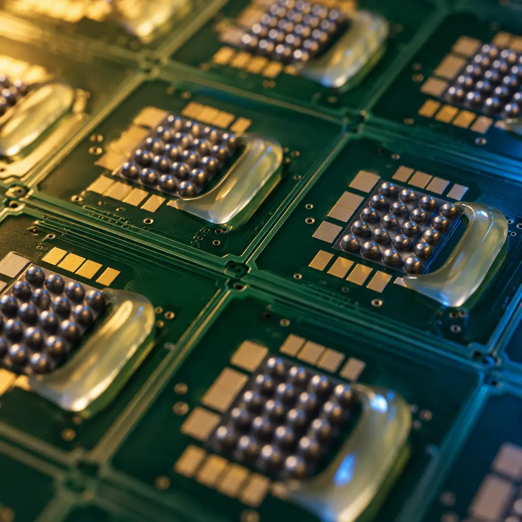
No-flow underfill (NUF) is the only underfill process that does not add a step to the line. Material is dispensed onto the board before placement, the package is placed into the wet deposit, and reflow simultaneously solders the joints and cures the encapsulant. On paper it is a straight win: no post-reflow dispense station, no 30–60 minute batch cure, no separate queue. On a real line it is the most temperamental process in surface-mount assembly, and the reason is that it asks two chemically opposed things to happen in the same oven at the same time.
The solder needs a clean, oxide-free metal surface and a flux that fully volatilises and leaves no residue. The underfill needs to gel, wet the joint field, and cure to a solid with a controlled modulus — and it must do all of that while the flux is doing its job, without either one blocking the other. Every no-flow failure traces back to that conflict somewhere. We run both no-flow and capillary underfill across the same 8 SMT lines and 4 DIP lines at Huaxing PCBA, and the difference in process ownership between the two is larger than most programme plans assume.
The Flux Compatibility Problem
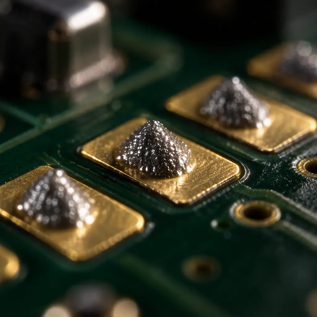
This is the single largest cause of no-flow underfill failure in volume production, and it is almost never specified during material selection. No-flow underfill is dispensed onto the same pads that carry the solder paste, or directly adjacent to them. During reflow, the flux chemistry activates, reduces oxides, and volatilises. The underfill chemistry is simultaneously gelling around the package. If the flux does not volatilise cleanly and completely before the underfill gels, the residue is trapped inside the encapsulant.
The result is not always visible on X-ray. Trapped flux residue under a package creates a localised region of low modulus and high ionic content — it degrades the mechanical coupling that is the entire purpose of the underfill, and it can form a conductive path under humidity bias. Both effects are slow, so they pass final test and fail in the field.
Run a Compatibility Matrix Before You Commit
No-flow underfill and solder paste are a coupled material system, not two independent selections. Before a production release you need a matrix that crosses every underfill candidate against every paste candidate and evaluates four things: gel time versus reflow profile, volatilisation completeness, post-reflow appearance and void content under acoustic scan. That is typically a 3 × 3 or 4 × 4 matrix — 9 to 16 combinations — and it is the cheapest failure to find at the bench.
Prefer No-Clean Pastes With Low Residue Characteristics
No-clean formulations are generally the right starting point for no-flow processes, because they are designed to leave minimal solid residue. Water-soluble and rosin-based activated pastes are much harder to pair, since they leave a larger solid fraction that competes with the underfill for the same gap volume. Our solder paste selection guide covers the residue characteristics that matter for encapsulation compatibility.
Do Not Assume "No-Clean" Means "Compatible"
No-clean is a statement about corrosivity and residue acceptability for a bare assembly, not a statement about chemical compatibility with an encapsulant. Two no-clean pastes with identical residue class can behave completely differently against the same underfill, depending on the activator system and solvent package. The matrix test is the only reliable arbiter.
Key Takeaway: Treat no-flow underfill and solder paste as a single qualified material system. If your process documentation names an underfill but not the specific paste, you have an unqualified process that happens to be passing today.
Reflow Profile: A Two-Constraint Window
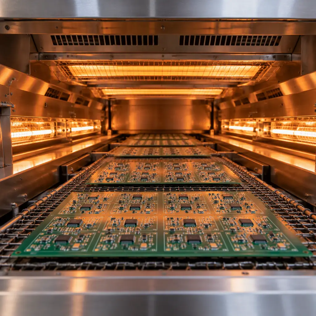
A standard reflow profile is designed around solder alloy melting behaviour. A no-flow profile has to satisfy the solder and the underfill simultaneously, which narrows the window from both ends. Heat too slowly and the underfill gels before the joints are fully formed, locking the package down while the solder is still liquid and producing incomplete or distorted joints. Heat too quickly and the flux cannot volatilise fully before the underfill film forms over it, trapping residue.
| Profile Stage | Standard Reflow | No-Flow Underfill | Constraint |
|---|---|---|---|
| Preheat ramp | 1.0–2.0 °C/s | 1.0–1.5 °C/s | Slower ramp gives flux time to volatilise |
| Soak (150–180 °C) | 60–90 s | 90–120 s | Longer soak for residue removal |
| Peak temperature | 235–245 °C (SAC305) | 235–245 °C | Unchanged, alloy-driven |
| Time above liquidus | 45–75 s | 45–60 s | Upper end risks over-curing underfill early |
| Cooling rate | 2–4 °C/s | 1–2 °C/s | Slower cooling reduces underfill stress and warpage |
The soak extension is the most important deviation from a standard profile, and it is the one most commonly resisted because it costs throughput. Extending soak from 75 to 110 seconds on a 60-second cycle time line is a real capacity decision. The alternative — running a standard profile and accepting residue entrapment — shows up as an elevated field return rate about six to twelve months later, which is a much worse problem to have.
Dispense Volume: The Error That Compounds
In a capillary process, dispense volume is self-correcting to a degree — excess material stays as a fillet, and insufficient material is visible as an incomplete fillet and can be topped up before cure. In a no-flow process there is no correction opportunity. The deposit is placed, the package is placed on top of it, and reflow locks in whatever geometry resulted. Dispense volume error is therefore a permanent defect.
The target is a deposit that, after placement compression, covers the full package footprint with a fillet at the edges and no material escaping beyond the package boundary by more than about 0.3 mm. Under-dispense leaves joints partially unprotected and produces a characteristically uneven fillet. Over-dispense wicks under adjacent components, contaminates nearby pads and can cause tombstoning on small passives as the material surface tension pulls against the placement.
Verify Deposit Volume With a SPI System, Not by Eye
A solder paste inspection system typically measures underfill deposits with the same optical method it uses for paste — area, height and volume — and that gives you a statistical process control dataset rather than an operator judgement. Volume control to ±10% is achievable; you cannot hold that by visual inspection at production speed. Our SPI process control guide covers how these limits are set and monitored.
Compensate for Placement Compression Explicitly
The package squeezes the deposit outward as it is placed. The final spread is a function of deposit height, placement force and dwell. If placement force is not controlled or varies between nozzle types, the same deposit program produces different fillets on different machines. Placement force belongs in the process spec alongside volume, not left as a machine default.
Set Up Keep-Out Zones on the Land Pattern
Underfill will flow until something stops it or it gels. Adjacent 0201 and 0402 passives sitting within about 0.5 mm of a CSP edge are at real risk of being partially encapsulated, which makes them unreworkable and can shift their position during reflow. Designing a keep-out around every CSP footprint is a layout decision, and it is far cheaper than discovering the problem in a production run. Our SMD versus NSMD pad design guide covers the mask-defined pad geometry that also helps contain flow.
Yield Economics: When No-Flow Actually Wins
No-flow underfill is usually justified on throughput, but the honest comparison has to include the yield difference and the engineering time the process consumes. A capillary line runs slower but is far more forgiving; a no-flow line runs at full speed but needs tighter control on four interacting variables.
| Factor | No-Flow Underfill | Capillary Underfill |
|---|---|---|
| Added cycle time | 0 s (folds into reflow) | 90–180 s dispense plus batch cure |
| Process variables under control | Volume, placement force, paste pairing, profile | Volume, pattern, substrate temperature |
| Typical first-pass yield at release | 97–99%, improves with SPC maturity | 99%+ from the first production lot |
| Engineering ramp time | 2–6 weeks to stable yield | 3–5 days |
| Rework feasibility | Very low | Very low |
| Best fit volume | Above roughly 50,000 units/yr | Below that, or any high-reliability build |
The break-even is real but higher than most programme plans assume. Below a few tens of thousands of units per year, the engineering ramp cost of stabilising a no-flow process usually exceeds the capacity value of the time it saves — which is why the sensible default for low and mid-volume work is capillary underfill, and no-flow is reserved for genuinely high-volume consumer programmes where the line is the constraint. The wider decision between underfill approaches is covered in our underfill selection guide.
Procurement tip: Ask for the no-flow qualification package, not just a sample board. The package should include the paste-underfill compatibility matrix, an acoustic scan of production samples, SPI volume capability data and a reflow profile with soak justification. An assembler running a stabilised no-flow process will have all four documents already.
Void Defects Specific to No-Flow Processing
No-flow voids differ from capillary voids in origin, and the fix is different in each case. Knowing which one you are looking at determines whether you change the profile, the pattern or the material.
Flux Volatilisation Voids
Appear as a cluster of small voids concentrated in the joint field directly under the package. Caused by flux volatiles released after the underfill has gelled over them. Fix: extend the soak, or change paste. Do not attempt to fix this by increasing dispense volume — that makes it worse by adding more material over the same trapped volatiles.
Entrapment Voids From Placement
Appear as one or two larger voids at the package centre or along a single edge. Caused by the package trapping an air pocket as it compresses the deposit, usually because the deposit is domed rather than flat. Fix: adjust dispense pattern to a flatter multi-dot deposit rather than a single central dome.
Moisture Voids From Board Bake
Appear diffusely across the whole encapsulated area, often with a foamed appearance. Caused by moisture outgassing from the laminate during reflow. This is the same root cause as in capillary processing and is resolved the same way — a proper pre-dispense bake. Our moisture control guide covers bake schedules and dry-pack handling for boards as well as components.
Shrinkage Voids From Cure Rate Mismatch
Appear as numerous small voids distributed through the fillet, not the joint field. Caused by curing too fast — the outer skin solidifies while the interior is still shrinking, tearing voids open. Fix: slower cooling and a gentler ramp. This is a profile adjustment, not a material change.
Deciding: No-Flow, Capillary or Molded
The three underfill processes optimise for different constraints, and the right choice is usually obvious once the qualification test and the annual volume are both known. A useful decision sequence:
High-Reliability Any Volume
Automotive, medical, aerospace and defence work goes to capillary underfill regardless of volume. The process window is wider, the qualification data is deeper and the risk of an undetected residue or void defect is materially lower. The added cycle time is absorbed by lead times that already run 7–10 days. See our automotive PCB requirements guide for what those programmes demand of the assembly process.
High-Volume Portable Consumer
Handheld and wearable products with annual volumes in the hundreds of thousands are the natural home of no-flow underfill. The drop-test requirement is the governing qualification, the volumes justify the engineering ramp, and line capacity is the binding constraint. Our consumer electronics guide covers the broader process expectations for that segment.
Multi-Die and Fan-Out Modules
Where several dies share a package or a reconstituted wafer needs full encapsulation, molded underfill is the only practical route. It requires dedicated tooling, so it only makes sense once the design is frozen and volumes are known. Details are covered in our advanced IC packaging substrate guide.
Prototype and Low Volume
Below roughly 10,000 units per year, the engineering ramp cost of no-flow is not recoverable. Capillary underfill — or, where the package is small and the environment benign, a qualified conformal coating with adequate gap penetration — is the rational choice. Our quick-turn manufacturing guide covers how prototype volumes are handled without sacrificing process qualification.
What to Ask Before Releasing a No-Flow Process
At Huaxing PCBA, no-flow and capillary underfill both run in-house alongside our full surface-mount and through-hole assembly, with acoustic microscopy, AOI, X-ray and SPI inspection on every build. When we release a no-flow process it is with a paste-underfill compatibility matrix, a documented reflow profile with soak justification, SPI volume capability data and a fresh acoustic scan — because those are the four documents that tell you whether the process is genuinely stable or merely has not failed yet. Send your Gerber and BOM and we will tell you honestly which underfill route your programme actually justifies.
