
You approve a quotation that includes a line item reading "tooling — solder pallet" with a four-figure number and no breakdown. It is not obviously optional, and it is not obviously necessary. A month later you discover the pallet was made for a product you are still building, that a design change invalidates it, and that a second revision means a second pallet. Understanding what a pallet actually does turns an opaque tooling charge into a normal engineering trade-off you can negotiate.
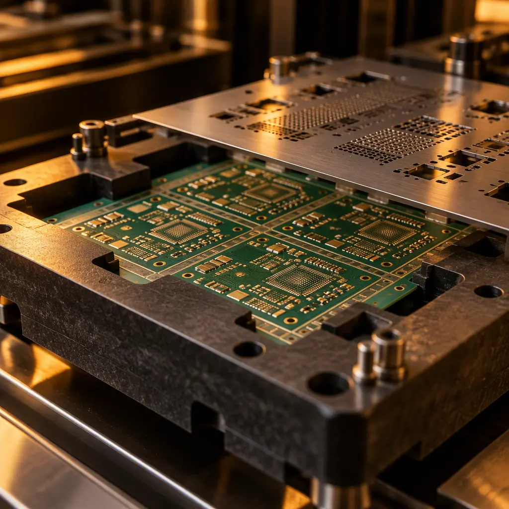
A solder pallet is a machined carrier that holds the PCB through the soldering process. It protects components that must not see solder, defines where solder is allowed to reach, supports the board so it does not sag or warp on a conveyor, and provides a stable mechanical reference for a process that is otherwise fighting gravity and thermal expansion at once. At Huaxing PCBA we build pallets in-house on our own machining centres, which means we can usually tell a customer within a day whether a pallet is required or whether a different process removes the need entirely.
Why Through-Hole Soldering Needs a Fixture at All
Reflow soldering is self-fixturing. Paste holds the component in place, surface tension centres it, and the board can be supported on pins or rails because nothing touches the solder side. Wave soldering is the opposite in every respect: the board rides over a pumped wave of molten solder that contacts the entire underside at once, and anything on that underside will be soldered whether you wanted it to be or not.
That single physical fact generates every pallet requirement. A pallet exists to answer four questions about the underside of your board.
Which areas must be masked from solder entirely?
Bottom-side SMT components already reflowed in a previous pass cannot be exposed to a solder wave — the wave would flood them and destroy the joints. The pallet's mask plate covers these regions with a machined or laser-cut opening only where wave contact is wanted. This is the primary function and the one that most often makes a pallet mandatory rather than optional.
How does the board stay flat and supported?
A large thin panel crossing a wave unsupported will sag, and sagging changes the contact geometry between solder and pad. Worse, the thermal gradient across an unsupported board drives differential expansion that shows up later as warpage. The pallet provides support pins and edge clamping at defined points. Board thickness is the key input — a 0.8 mm panel needs support density that a 2.0 mm panel does not, as covered in our PCB board thickness selection guide.
How are connectors and tall parts protected?
Through-hole connectors, terminal blocks, relays and sockets often have plastic bodies that cannot survive a 250 °C wave. The pallet's hold-down fingers retain these parts during the pass and the mask plate prevents solder flooding the body. Retaining a connector is genuinely difficult — you need positive downforce without crushing the housing, which is why hold-down design is where most of the machining time goes.
Does the pallet survive the process itself?
It sits over molten solder repeatedly, so the material must hold dimensional stability across hundreds of thermal cycles without warping or shedding particles. A warped pallet changes the mask openings relative to the board and produces solder defects that look like a process problem but are actually a tooling failure.
Pallet Materials and What You Are Paying For
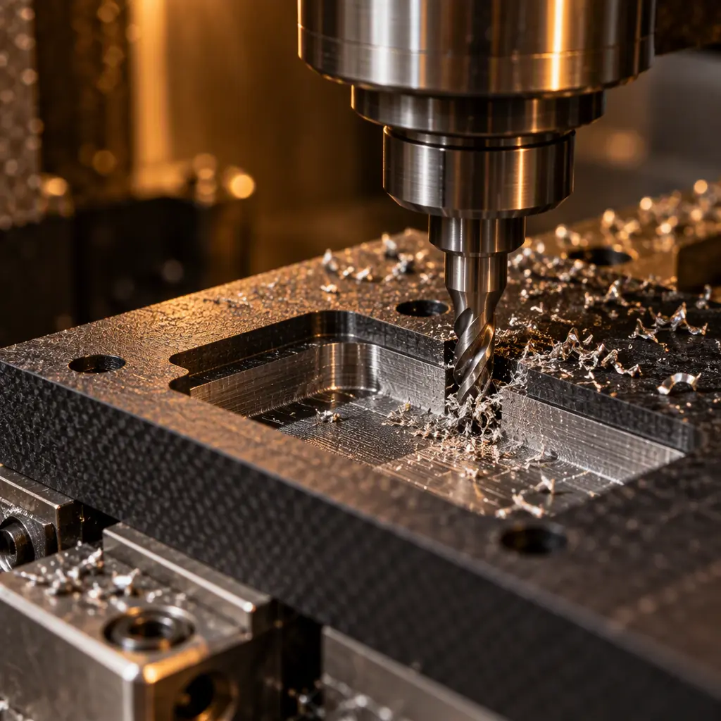
Pallet material choice drives both the tooling cost and the pallet's service life, which in turn determines whether the tooling is a one-off charge or a recurring amortised cost across a production run.
| Material | Typical service life | Where it earns its cost |
|---|---|---|
| FR-4 / phenolic laminate | Low hundreds of passes | Prototype and low volume; cheapest to machine, degrades fastest |
| Machined aluminium | Long, with recoating | High-volume single product; good thermal stability, needs insulation where it touches the board |
| Composite (synthetic stone / Durostone type) | Thousands of passes | Mainstream high-volume production; the usual default for stable programs |
| High-temperature engineering polymer | Medium to long | Programs needing light weight or complex 3D-machined retention features |
The commercial pattern is straightforward. Laminate tooling is cheap to make and expensive to own across a long run, because it warps and needs replacing. Composite and aluminium tooling cost more up front and far less per pass. If you are building 500 units, laminate may well be the rational choice; if you are building 50,000 across three years, paying for composite at the start is the cheaper decision. Ask your supplier to quote both and to state the assumed pass count — the assumption is where the savings hide.
Key Takeaway: The tooling charge is not a fixed feature of the product; it is a function of the material life you choose against the volume you expect. Ask for the assumed number of passes behind any pallet quotation. A supplier quoting composite tooling for a 500-piece build is over-engineering; a supplier quoting laminate for a three-year program is passing you a recurring cost disguised as a one-off.
What Actually Drives Pallet Cost
Once material is settled, the cost is dominated by machining complexity and the number of features that have to be positioned accurately relative to the board. The drivers, roughly in order of impact:
Number and complexity of mask openings
Each selective opening is a machined feature with a positional tolerance relative to the board datum. A pallet with 40 small openings around fine-pitch connectors costs several times one with three large windows, even though the material is identical. Consolidating openings where the design allows is the most effective cost lever available to a designer.
Hold-down and retention features
Every connector that needs positive retention adds a machined finger, a spring element or a clip, each fitted and tested by hand. A board with twelve different connectors that must be held during the wave pass is a genuinely complex tool. Standardising on a smaller number of connector families across your product range reduces pallet complexity permanently — this is a design decision with a tooling payoff.
Panelisation strategy
Pallets are made for the panel, not the individual board. Changing your panel layout to suit fabrication efficiency can invalidate pallet tooling, and conversely a clever panel design can let one pallet carry more board variants. Our guides to panelisation cost optimisation and panel utilisation and nesting cover the trade-offs — the tooling consequence is worth weighing alongside the material yield gain.
Revision churn
A pallet is made to a specific board revision. If your design is still moving, you will pay for the pallet more than once, and the second purchase is usually the moment buyers notice the recurring nature of the cost. Freezing the mechanical outline and connector positions before ordering tooling is the single most effective way to avoid paying twice. Our engineering change order guide covers how to control revisions so tooling stays valid.
When Selective Soldering Removes the Pallet Entirely
Selective soldering deposits solder only at the specific through-hole locations that need it, using a small nozzle rather than a full-board wave. Because the process is inherently local, it largely removes the reason a pallet exists in the first place.
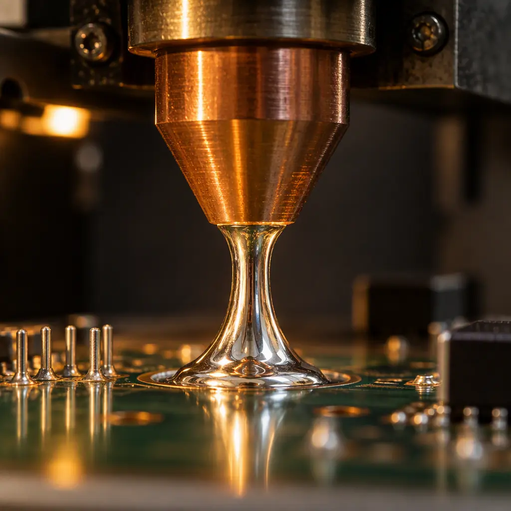
The trade is process time against tooling cost. Selective soldering is slower per joint than a wave pass, because the nozzle travels from point to point. For a board with a handful of through-hole joints alongside dense bottom-side SMT, selective is often plainly the better answer: no mask plate, no retention fingers, no tooling charge, and no risk of a wave flooding components that should have been left alone. For a board with hundreds of through-hole joints on an open underside, the wave is far faster and a pallet is the right investment.
The decision rule we apply is roughly this: if the through-hole joint count is low and the bottom side is already populated with reflowed SMT, selective soldering usually wins on total cost including tooling. If the underside is largely open and the joint count is high, a pallet and a wave pass will be cheaper per unit and the tooling amortises quickly. Our comparison of wave soldering versus selective soldering works through the crossover point in detail, and double-sided and mixed-technology assembly covers the reflow-order constraints that often decide the question before cost even enters it.
| Scenario | Likely best process | Tooling implication |
|---|---|---|
| Few THT joints, dense bottom-side SMT | Selective soldering | No pallet required |
| Many THT joints, open underside | Wave soldering | Pallet amortises well over volume |
| Mixed, with connectors needing retention | Wave plus pallet | Pallet mandatory regardless of joint count |
| Prototype, 10 to 50 units | Selective or hand | Avoid tooling entirely; see prototype vs production |
| High thermal-mass press-fit or heavy copper | Selective with preheat | No pallet, but longer cycle; see press-fit technology |
Hand Soldering: The Option Buyers Underestimate
For low volumes and low joint counts, qualified hand soldering to IPC J-STD-001 is often dismissed as a quality risk when in fact it is the economically correct answer. The concern is legitimate but manageable: hand soldering quality depends on operator certification and on a documented process with defined iron tip geometry, temperature and dwell time. Where those exist, hand soldering a handful of connector joints on a 50-piece build is cheaper and faster than commissioning tooling. Our guide to J-STD-001 solder assembly requirements covers what a compliant hand-soldering process requires, and low-volume PCB assembly covers where the volume boundaries sit.
Factory reality check: The most common tooling waste we see is a pallet ordered for a product that then changed shape. Customers frequently freeze the electrical design and leave the mechanical outline open — connector positions, mounting holes, board edge profiles — which is exactly the set of features a pallet is machined around. Freeze the mechanical drawing before you authorise tooling, even if the circuit is still being tuned. Schematic changes rarely invalidate a pallet; connector moves almost always do.
How to Specify and Negotiate Pallet Tooling
Require a pallet drawing for approval before machining
The drawing should show mask openings, support pin positions, hold-down features and the board datum. Approving the pallet drawing is your last cheap opportunity to catch a misread connector position — after machining, corrections are a new tooling charge. Request it even when you have no intention of reviewing it in detail; the requirement itself changes how carefully it is prepared.
State the expected pass count and lifetime
This converts the tooling decision from an opaque number into a comparison. A supplier who knows you expect 40,000 passes will quote material accordingly, and you can evaluate whether the per-unit amortised cost is reasonable against the alternative processes.
Clarify ownership and portability
Confirm whether the pallet is yours, whether it transfers if you move the program, and whether the drawing will be released to you. Tooling that exists only in your supplier's machine shop is a switching cost you have paid for without noticing — relevant to our supplier transition guide. Also confirm the spare-parts position: support pins and retention fingers wear and need replacement, and those should be quotable items rather than surprises.
Ask what happens on a design revision
Find out before you need to know. A minor revision that moves one connector may be repairable by re-machining an existing pallet at a fraction of the new-tool cost, or may not. Establishing that policy in advance removes the negotiation from an already stressful schedule moment.
Compare the tooling line against the selective-solder alternative
Ask explicitly: what would this cost if we selective-soldered it instead, with no tooling? The answer is frequently close enough that process time, not tooling, becomes the deciding factor — and having the comparison in hand makes the tooling charge negotiable rather than fixed.
Summary and Next Steps
A solder pallet is not overhead — it is the physical answer to four questions about the underside of your board: what must be masked, what must be supported, what must be retained, and what must survive the process. Its cost is driven by opening count, retention complexity, panelisation and revision churn, and its material should be chosen against the number of passes you actually expect. Where through-hole joint counts are low and the bottom side is populated, selective soldering often removes the tooling requirement entirely, and that comparison should be in front of you before you approve a pallet charge.
At Huaxing PCBA we machine pallets and carriers in house and will tell you when you do not need one, because a tooling charge we talk a customer out of is cheaper for both of us than a fixture that gets replaced twice. Our facilities hold IATF 16949 and ISO 9001 certification, with wave and selective soldering alongside 8 SMT lines. Read our wave versus selective soldering comparison or send your assembly drawing and ask for both process options priced — quote with free DFM review in 24 hours.
