
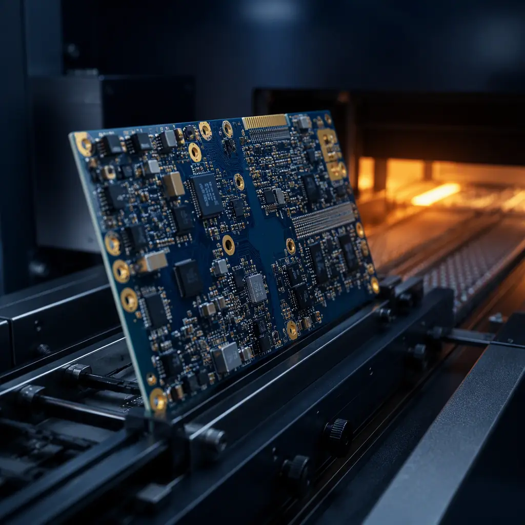
The economics are hard to argue with: put components on both sides of a board and you get more function in the same footprint, add thermal and shielding room, and often remove a layer from the stackup. But double-sided SMT is not "SMT, twice." The second pass reflows the whole board again, which means the components you placed on the first side now face the problem of staying put while gravity and reflow pull them the wrong way. For most designs the solution is a small dot of adhesive; for heavy or dense designs it is a deliberate process sequence with a specific over-mold or a selective approach. Mixed-technology boards, SMT and through-hole on one panel, add a second friction point.
This is a design and sourcing decision, not just an assembly detail. At Huaxing PCBA we run 8 SMT lines and 5 DIP lines together, so double-sided and mixed-technology work is in our daily flow. We process 8 million placements per day, and a large share of those boards are two-sided. Here is the process logic that keeps them on the board and out of the scrap bin.
Why the Second Side Is the Hard One
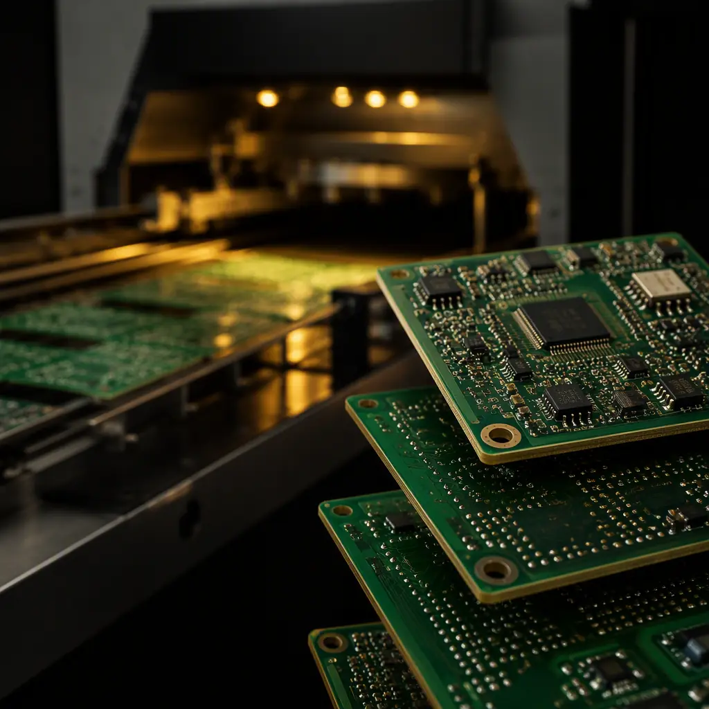
When a board goes through reflow, the solder paste melts, the solder reflows, and then the board cools. On a single-side board, gravity holds every component onto the paste until the solder freezes. On a double-side board, when you flip it for the second pass, the components from the first side are now underside face-down with only the now-solid solder joints holding them. As the board heats to reflow temperature, that first-side solder re-melts. And if a component is heavy or the joint is small, it can slide, tombstone, or fall off entirely.
The glue vs no-glue decision
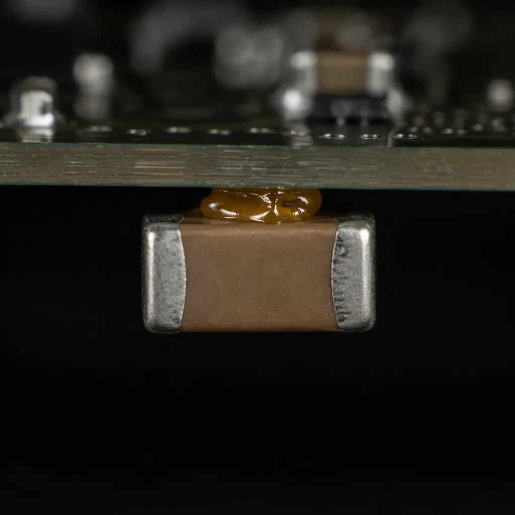
The standard fix is a dot of high-temperature surface-mount adhesive (SMA) under each first-side component. The adhesive cures quickly (usually UV or heat), and it holds the part through the double reflow. But the adhesive is the cost. It adds a glue-dispensing step, a cure station, a second stencil for some processes, and careful selection because the adhesive can affect thermal behavior and cleanability. On the other hand, "no-clean" double-sided flows omit the glue by placing only reflow-safe, low-mass components on the underside and reflowing them once, which is the strategy for high-value, fine-pitch boards.
Heavy components are the danger
Large electrolytic capacitors, connectors, transformers, and heatsinks have far too much mass for a first-side reflow. A heavy part can pull a pad off, crack a joint, or shift during the second pass. The rule is simple: heavy components and through-hole connectors belong on the side that reflows once, or on the "bottom" of a single-side flow. This is where design-for-assembly truly pays off. Deciding component placement before the board is laid out.
Board thermals: the second heating cycle
The board and its already-placed components are heated a second time to peak reflow, which stresses thermal-cycling-sensitive parts and can tarnish a gold surface. Avoiding two full reflow peaks is one reason many high-reliability designs put all surface-mount parts on one side and whatever through-hole remains on the other. For sensitive BGA parts this matters even more, see our BGA assembly guide.
Key Takeaway: The glue-vs-no-glue call is the crux of a good double-sided flow. You can either add the adhesive step and place freely, or you design the underside for low-mass, reflow-safe parts and skip the adhesive. More boards than you think are rejected just because the process order was chosen after the layout was frozen.
The Two Standard Double-Sided Flows
Every two-sided board follows one of two proven sequences. The one your manufacturer uses depends on your component mix and your reliability requirements:
| Attribute | Adhesive double-sided flow | Two-pass (no-adhesive) flow |
|---|---|---|
| Sequence | Side A: paste + dispense adhesive + place; cure glue; reflow | Side A: paste + place; reflow; flip |
| Side B | Paste + place; reflow (parts held by glue) | Paste + place; reflow (low-mass parts only) |
| Component mass limit on underside | Moderate, glue provides the hold | Low, solder joints alone must hold |
| Extra step / cost | +glue dispense, +cure, +stencil | None |
| Best for | Mixed sizes, denser boards | High-value / fine-pitch, small underside parts |
The two-pass flow is cleaner but only works when every component on the concave side is small enough to hold through the second melt. If your underside has a connector, an inductor, or a medium-sized part, the adhesive flow is the safe answer. Our SMT vs through-hole comparison explains the wider selection logic.
Mixed-Technology Boards: SMT + Through-Hole Together
Many real products aren't purely SMT. They carry a mix of surface-mount parts and through-hole components, power connectors, terminal blocks, large caps, sockets. The two technologies are assembled differently, and how you sequence them decides cost and yield.
Order of operations
The standard sequence is SMT first, then through-hole. SMD parts go on both sides through one or two reflow passes; the through-hole parts are soldered afterward with wave or selective soldering. The reason is thermal and mechanical: reflowing after the through-hole parts are already in place would stress them, and wave/selective soldering can re-melt SMT joints or wick solder into places you don't want it.
Where through-hole soldering fits
Wave soldering handles a large number of THT joints in one pass but has a big footprint constraint and can leave solder on areas you don't want. Selectively soldering jets solder onto individual through-hole pins with a mini-wave, which is why it dominates on boards that are mostly SMT with a handful of THT parts. For the trade-off between the two, see our wave vs selective soldering guide.
Masking and fixturing
When you mix technologies, you need fixture and masking discipline: spray flux or wave only where you want it, mask connectors and through-board solder you don't want coated, and prevent solder wicking up SMT leads. This is a real planning cost, and it's why mixed-technology boards are priced differently from a clean SMT order.
Procurement Tip: Tell your assembly partner the component count by technology up front. "30 SMD, 12 through-hole" changes the process plan and the price a lot more than the raw part count suggests. A clear parts list with a THT count lets your supplier pick wave or selective and quote accurately.
Stencil, Paste and Spacing for Two-Sided Boards
Double-sided and mixed boards change the stencil and spacing rules. These are the details that stop a board from passing on the first side and failing on the second:
Aperture design through the second pass
Paste deposits on the second side must hold the component until reflow, and they are subject to the same board heating and any flux migration from side A. Stencil apertures and paste volume may need tuning for the second side, especially for small 01005 and 0201 parts. Our SMT stencil design guide covers aperture rules in depth.
Spacing and keep-outs for the underside
First-side parts that sit under the board when it flips must not interfere with the second-side placement, the fixture, or the conveyor. This is a layout decision: keep the underside free of tall first-side components and give the second-side parts adequate clearance. DFM review before you tape out catches these.
Fiducials and handling
The board is inverted and re-fed, so fiducials on both faces are important, and the assembly must survive handling and edge clamping on both passes. Warpage becomes a real concern. A warped board can shift components on the second pass, so a reflow warpage check is worth doing before committing to a two-sided flow.
The 10-Second Buyer's Checklist
Key Takeaway: Double-sided SMT lives and dies on the glue-vs-no-glue call, and mixed-technology success hinges on sequencing SMT before through-hole and choosing wave vs selective soldering. Decide the process before the layout is frozen, give your supplier a component mix by technology, and verify warp, spacing and keep-out early in DFM.
Summary, Plan the Process Before You Freeze the Layout
Two-sided SMT is a density win only if the process is designed alongside the board. By choosing the adhesive or two-pass flow deliberately, sequencing mixed technology correctly, and respecting spacing and warp constraints, you get the density without the dropped components, rework and field failures that plague a late process change.
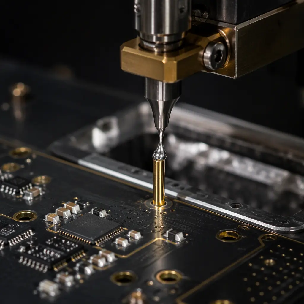
At Huaxing PCBA we run 8 SMT lines and 5 DIP lines with automated glue dispensing, UV adhesive curing, and wave and selective soldering for mixed-technology boards up to 32 layers. We review your component mix and process sequence for free before you commit, so the board we quote is the one we can build reliably. We are ISO 9001, IATF 16949 and UL certified. Upload your files for a quote or talk to our engineering team about your double-sided or mixed-technology build.
