
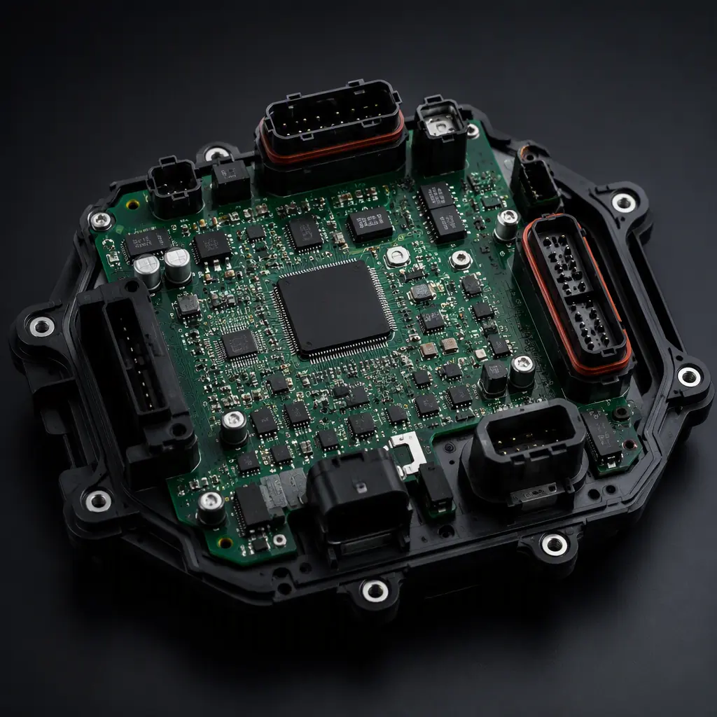
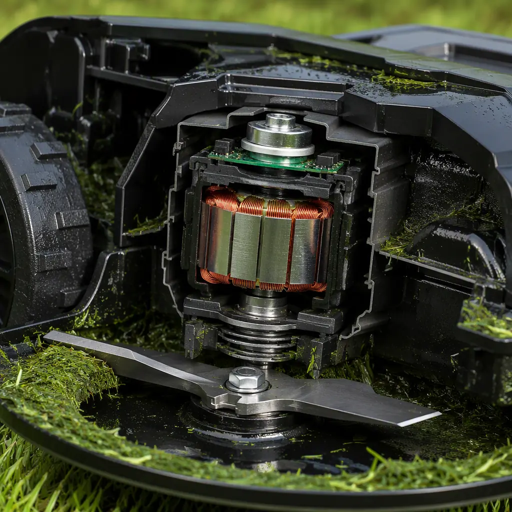
A robotic mower shares DNA with a robot vacuum, but the environment is a different species of problem. The board must keep working through rain splash (IPX4 at minimum), grass dust that packs into every crevice, -10 °C to 50 °C temperature swings, UV-degraded plastics, and vibration from a blade spinning at 3,000+ RPM while the machine bounces across uneven turf. The failure modes are not subtle: a single uncoated connector corrodes in one wet season, and a poorly protected blade motor controller can fail mid-mow, leaving a 4 kg robot stranded in the yard with a spinning blade.
This guide covers the three sections that decide whether an outdoor robot survives: board-level waterproofing and conformal coating, the BLDC blade and drive motor electronics, and RTK-GPS navigation with its antenna and EMI constraints. It closes with the manufacturing and test flow that proves waterproofing and reliability at volume. Huaxing PCBA assembles robot and outdoor electronics across 8 SMT lines, the same rules apply to our robot vacuum boards and every AGV/AMR control board we build.
Waterproofing Strategy: Coating, Connectors and Component Selection
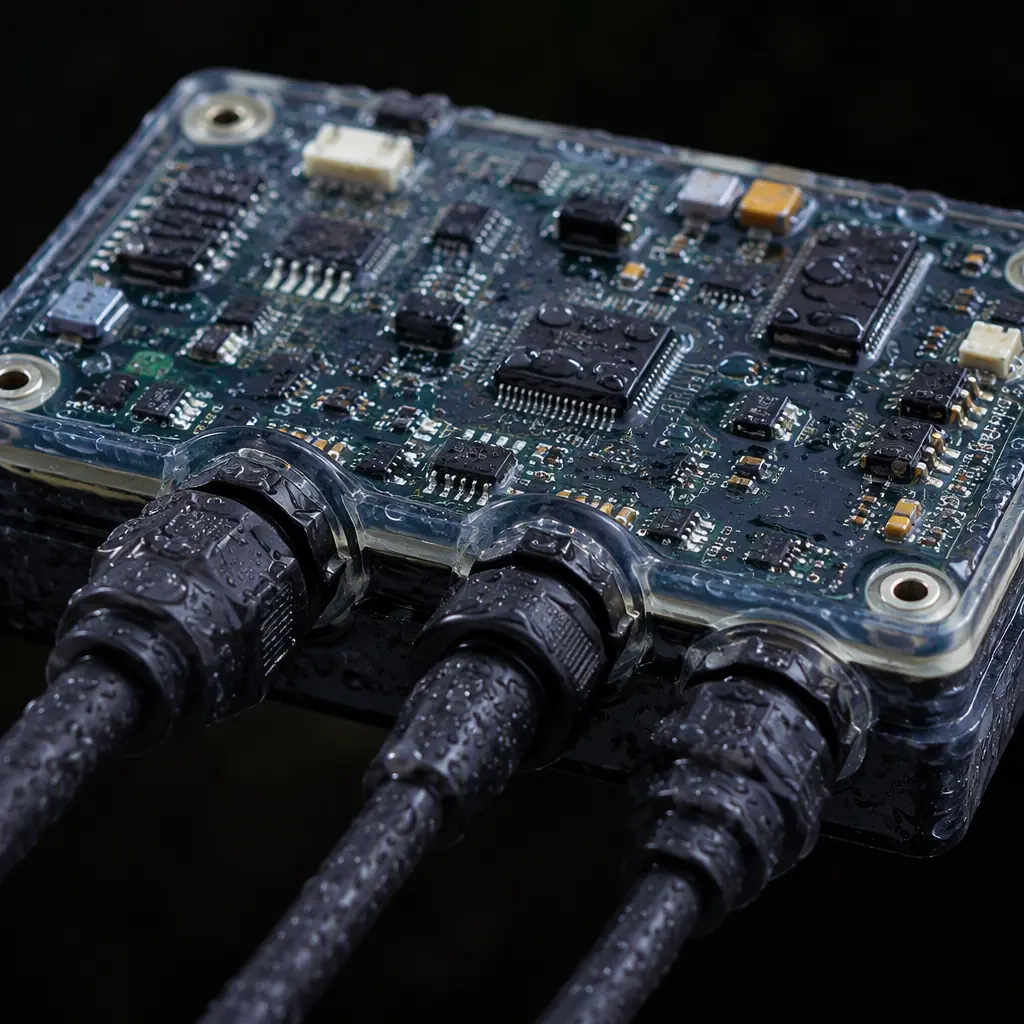
Waterproofing an outdoor robot board is a layered defense. Conformal coating protects the PCB surface, but the specification is decided by where the board sits in the machine and how it is sealed. A mower mainboard typically targets IPX4 (splash) to IPX5 (water jet) depending on whether it lives above or below the deck line.
Specify coating thickness and coverage, not just "conformal coated"
Acrylic coating (IPC-CC-830) at 25–75 µm is the standard for robot boards; silicone or parylene is specified for boards exposed to condensation. The coating must cover the component bodies and the solder joints at the leads, but not the connectors, test points, or the blade motor's high-current terminals. Masking strategy is part of the PCB design. Define the no-coat zones in the assembly drawing, or the CM will coat everything and break your test points. Our conformal coating guide covers material selection and masking rules in detail.
Sealed connectors with gaskets, and potting for exposed sub-boards
Every wire-to-board connector on a mower must be a sealed type (IP67-rated connectors or gasketed headers), because coating cannot protect a connector interface. Sub-boards that sit in the wet zone, the blade motor controller, the charge contact board, should be potted with polyurethane or epoxy rather than coated. Potting adds weight and complicates rework, so use it only where water ingress is guaranteed. See our potting and encapsulation guide for material and process trade-offs.
Choose corrosion-resistant finishes and closed components
ENIG or ENEPIG surface finish resists the chloride and fertilizer chemistry found on lawns far better than HASL. Select connectors, relays and switches that are sealed or closed-construction (no open vents), and derate electrolytic capacitors for the 50 °C+ internal ambient. A capacitor rated at 105 °C with 5,000 h life at rated temperature derates to roughly 20,000 h at 85 °C ambient, which is the practical target for a 3-5 year mower.
Key Takeaway: The waterproofing spec is a system decision, not a coating line item. Decide the IP target per board zone, then choose coating + connectors + potting accordingly. A coated board with unsealed connectors fails exactly like an uncoated one.
Blade and Drive Motor Electronics: BLDC Control Under Load
The blade motor is the highest-risk subsystem on a mower. It runs at 2,000–4,000 RPM under a cutting load that varies with grass density, and it must stop within milliseconds when the mower is lifted or tipped. That is a hardware safety requirement, not a firmware nicety. Most mowers use a sensorless BLDC motor driven by a 3-phase inverter on the mainboard.
Size the inverter for stall current, not running current
A 20 V blade motor draws 3–5 A running but 15–25 A at stall (blade jammed against a root or rock). The MOSFETs, bus capacitance and copper must handle the stall pulse for the ~1 second it takes the controller to detect and reverse or stop. Use MOSFETs rated 2× the max stall current, a bus capacitor bank sized for the switching ripple, and low-side current sensing with a comparator-based hardware overcurrent trip. Firmware response is too slow for a blade jam. The BLDC controller design guide covers inverter layout and current sensing in depth.
Hardware safety chain: lift, tip and blade-stop
Lift/tip detection (reed switch, Hall sensor or IMU) must be wired into a hardware interlock that shorts or brakes the blade motor phases, not just a flag the firmware reads. The braking circuit (typically a low-side shunt or motor-short brake) must stop the blade within the 3-second requirement of EN 50636 / UL 2595 blade-stop tests. Design the brake path as a separate copper area with its own current capability; it carries the full stall current for a few hundred milliseconds on every lift event.
Thermal management for continuous full-load mowing
The drive inverter dissipates 3–8 W continuously in thick grass. The MOSFETs need a thermal pad with a via array to a bottom-side copper pour, and the board should be positioned in the air flow path of the mower body. If the mainboard is sealed in a waterproof enclosure, that trapped heat is a design input, you may need a heat spreader to the chassis or a larger board area. Our PCB thermal management guide has the via and copper budget calculations.
Navigation: RTK-GPS, IMU and the Antenna Problem
Wire-free boundary mowers rely on RTK-GPS for centimeter-level positioning, with an IMU for slope detection and collision sensors for the edges the satellite signal cannot see. The PCB challenge is that the RTK antenna needs clear sky, the electronics need shielding, and the blade motor is an EMI source sitting centimeters away.
Antenna placement: top deck, clear of copper and motors
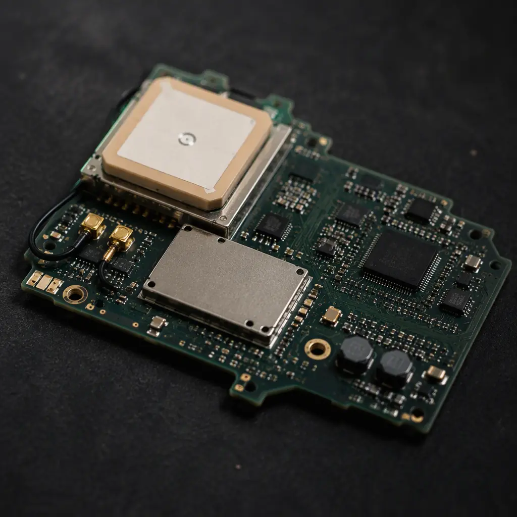
The RTK/GPS antenna (active patch or helical) belongs on the top deck of the mower, mounted on a ground plane with a clear view of the sky. The antenna feed must be a 50 Ω controlled-impedance trace (or a short coaxial pigtail) from the antenna to the receiver module, kept away from the blade motor wires and the inverter. The receiver module itself should sit in a shielded can on the mainboard. GPS antenna and RF layout rules are covered in our PCB antenna design guide.
Isolate the IMU from motor vibration and EMI
The IMU (6-axis, used for tilt detection and dead-reckoning in RTK dropouts) is sensitive to both mechanical vibration and electrical noise. Mount it away from the blade motor, add a soft-mount or foam isolation, and keep the I²C/SPI bus short with pull-ups to the IMU's own rail. Vibration is a PCB reliability issue too, the full test profile is covered in our vibration and shock testing guide.
EMC: the blade inverter is the aggressor
A 3-phase inverter switching 20 V at 20–30 kHz radiates through the motor cables, which act as antennas. Plan for a common-mode choke on the motor wires at the board edge, keep the motor cable's return path tight, and place the RF and GPS sections on the opposite side of the board from the inverter. Pre-compliance EMC testing in the prototype phase is cheaper than redesigning the layout after certification, the EMC/EMI compliance guide walks through the standard test sequence.
Battery and Charge Management for a Seasonal Product
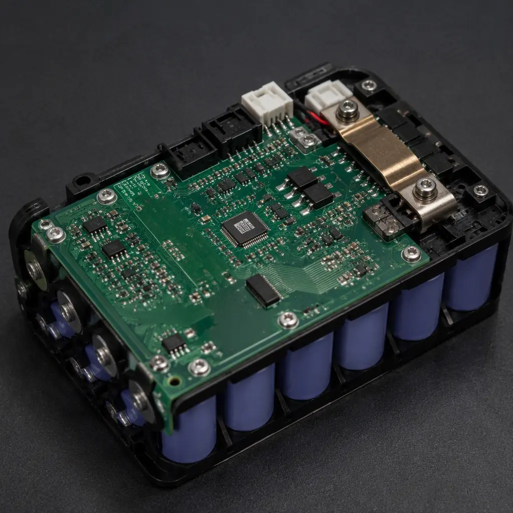
Most mowers run on a 20–40 V Li-ion pack (4S–10S), charged from a dock with contact or induction charging. The battery sits inside the mower body, which means it sees the full outdoor temperature range and the blade's vibration.
BMS on the pack, charge control on the mainboard
The pack carries a BMS for cell balancing, over-current and over-temperature protection; the mainboard handles the charging algorithm and the dock communication. The charge path needs reverse-polarity protection and a contactor or FET that disconnects the pack on fault. For a 10S pack the balance and monitoring circuitry must be rated for the pack voltage with proper creepage, see our EV battery management guide for the isolation and safety layout rules that scale down to mower packs.
Charge contacts are a corrosion hotspot
The dock's charge contacts are exposed to rain and grass moisture every docking cycle. Use gold-plated contacts, and consider a relay or FET that only energizes the contact pads during charging, this prevents electrolytic corrosion between the pads when wet. The charge contact board is a classic candidate for potting or a separate sealed sub-board.
Standby current matters more than peak efficiency
A mower sits in its dock between mows, often for days. The total standby draw (BMS, charge controller, wake circuit) should be under 1 mA so the pack does not drain while parked. Specify low-quiescent regulators and a wake-on-dock or wake-on-schedule circuit that keeps the main MCU in deep sleep. The portable power station PCB guide covers low-standby power design patterns for battery products.
Manufacturing and Test for Outdoor Robots
Outdoor robot boards need a test flow that proves the waterproofing and reliability claims before the product ships. Beyond the standard SMT inspection, the mower board typically requires:
| Test | What It Catches | Where It Runs |
|---|---|---|
| ICT / flying probe | Opens, shorts, wrong values | Post-reflow, pre-coating |
| Coating inspection | Missing coverage, masking violations | UV / visual station after coating |
| High-pot (hipot) | Coating breakdown on high-voltage sections | Charge path, motor terminals |
| Motor drive test | Phase balance, stall detection, brake timing | Dynamometer or loaded bench |
| Thermal cycle + vibration | Solder joint and component survival | Sampling, per production lot |
Sequence coating after electrical test, not before
ICT and functional test must run on the bare board, then the board is coated, then a post-coating smoke test verifies the coated board still functions (coating can wick into relays, connectors or test points despite masking). The inspection methods guide covers AOI/x-ray placement in the flow.
Verify blade-stop timing on every unit
The safety chain (lift detection → brake → blade stop) must be tested on every assembled unit, not sampled, it is a certification-relevant safety function. Automate the test: lift the deck, measure stop time, log the result with the serial number. Batch records let you trace a field safety issue to a production lot.
Run the reliability tests on a sampling plan
Thermal cycling (-20 °C to +60 °C), vibration and a wet-splash functional test should run on a per-lot sample (e.g., 5 units per 1,000). These tests catch process drift, a change in coating thickness, a different batch of connectors, before it reaches the field. The burn-in and ESS testing guide has the sampling math and duration rules.
Building a Mower That Comes Back to Its Dock
The order of design for an outdoor robot is: define the IP strategy per zone first, then the safety chain for the blade, then the RF and antenna plan, then the battery and charging. Each decision is a PCB decision, coating zones, inverter copper, antenna keep-out, BMS isolation. Verify waterproofing with a wet test in the prototype phase, verify blade-stop on every production unit, and sample the thermal and vibration profile per lot. The robots that make it through a season are the ones whose boards were designed for the rain from the first layout.
Huaxing PCBA assembles robot lawn mower and outdoor electronics with IPX4-ready coating lines, sealed connector assembly and serialized safety test logging across 8 SMT lines. Read our AGV/AMR guide for the navigation side of mobile robots, or send your BOM and IP target . We'll return a DFM review covering coating zones, inverter thermal design and antenna placement with your quote within 24 hours.
