
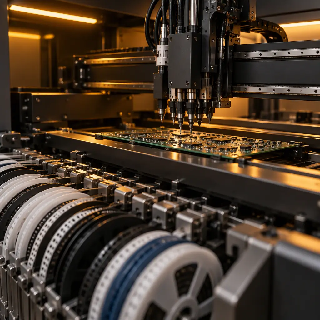
When a contract manufacturer says "we run Yamaha" or "we run ASM" or "we run Fuji," the implication is that the brand is the capability. It is not. Two lines with identical placement machines can produce very different yields, because the capability that determines whether a 0.4 mm-pitch QFN lands correctly is not the machine's brand — it is the placement capability index the line actually holds at volume, the feeders loaded on it, and the discipline of the tape-and-reel handling behind them.
For a buyer, this matters because placement is upstream of everything. A component placed outside its pad tolerance either fails inspection, fails electrically later, or — worst of all — passes inspection and fails in the field. The machine's advertised speed and accuracy are inputs to that outcome, but they are not the outcome. The purpose of this guide is to give a buyer the vocabulary to ask about placement capability in a way that produces a useful answer.
It sits inside the wider SMT process series on this site: the placement step feeds the printing and reflow steps covered in our guides to first-pass yield and fine-pitch assembly, and it depends on design decisions from design for assembly and DFA. Placement capability is where those threads meet on the line.
At Huaxing PCBA we run placement across 8 SMT lines under IATF 16949 and ISO 9001, from high-mix low-volume prototype runs to volume production, and we qualify placement per board family rather than quoting a single machine statistic. That distinction — per board, at volume — is the whole point of this article.

Placement Accuracy vs Placement Cpk — What the Number Actually Means
The specification sheet gives two figures that are easily confused, and the confusion is exactly what a buyer needs to avoid. Accuracy is how close the machine can place on average. Cpk is how consistent that placement is against the tolerance you actually need. A machine can have excellent accuracy and a mediocre Cpk, and the Cpk is the one that predicts defects.
Placement accuracy. Usually quoted as a linear value at a specified speed and component size — for example, ±35 µm at 3 sigma for chip components at a given placement rate. It describes the centre of the placement distribution. It says nothing about how wide that distribution is, and a wide distribution is where out-of-tolerance placements come from.
Placement Cpk. The capability index measures the distance between the placement distribution and the pad tolerance, expressed in standard deviations. A Cpk of 1.33 is a common acceptance floor for a critical characteristic; 1.67 is a stronger target for fine-pitch work. Cpk is meaningful because it folds in both the centring and the spread, and it is measured against a specific pad geometry — which is why a single "Cpk" number quoted without the component and pad it refers to is close to useless.
In practice, the characterisation of placement equipment capability follows a defined method rather than a marketing claim — IPC-9850 is the standard that describes how placement equipment performance should be measured, including what component types and conditions the measurement applies to. A supplier that can point to how its placement capability was measured, and on which board family, is giving you evidence; one that quotes a bare accuracy figure is giving you a datasheet excerpt.
Key Takeaway: Accuracy is where the machine places on average; Cpk is how reliably it stays inside the pad tolerance. A tightly centred process with a wide spread can still drop a high volume of out-of-tolerance placements. Ask for Cpk on a board family like yours, not a headline accuracy number.
Feeder Types and Why Feeders Drive Defects
The feeder is the interface between a reel of components and the nozzle that picks them. It is the least glamorous part of the line and one of the most common sources of placement defects, because a feeder that presents a component slightly out of the pick window causes the nozzle to pick it offset — or to pick it and drop it, or to pick a damaged part.
The main feeder families and where each fits:
Tape-and-reel feeders. The dominant format for surface-mount components, delivering parts from a pocketed carrier tape sealed with a cover tape. Paper tape suits small chip components; embossed plastic tape is used for larger or taller parts and for moisture-sensitive devices. Tape feeders are available as mechanical or electric; electric feeders index more precisely and are the norm on modern high-mix lines because their pick position is repeatable run to run.
Tube feeders. Components slide down a tube and are picked from the end. They suit parts that are not supplied on tape — older through-hole or odd-form components, some connectors and modules. Tube feeding is slower and more prone to jams and to components presenting at an inconsistent angle, so it is used where tape is unavailable rather than by preference.
Tray and matrix feeders. Components arrive in a moulded tray in a fixed grid, and the machine indexes over the tray. This is the format for large or fragile parts — BGAs in some large packages, connectors, shields, module assemblies — where tape would be impractical or would damage the part. Tray feeding is expensive in line time because the machine moves to the part rather than the part arriving at a pick point.
Bulk and vibratory feeders. Used for small, robust parts where orientation can be set mechanically. Rare in modern SMT work but worth knowing because a supplier that resorts to bulk feeding for a critical part is signalling a sourcing or packaging problem worth asking about.
The feeder type matters to a buyer for a specific reason: it determines the machine time per placement and the failure modes on the line. A design dominated by parts that must be tray-fed will run slower than one that is tape-fed throughout, and a supplier quoting cycle time without accounting for feeder mix is quoting an optimistic number.
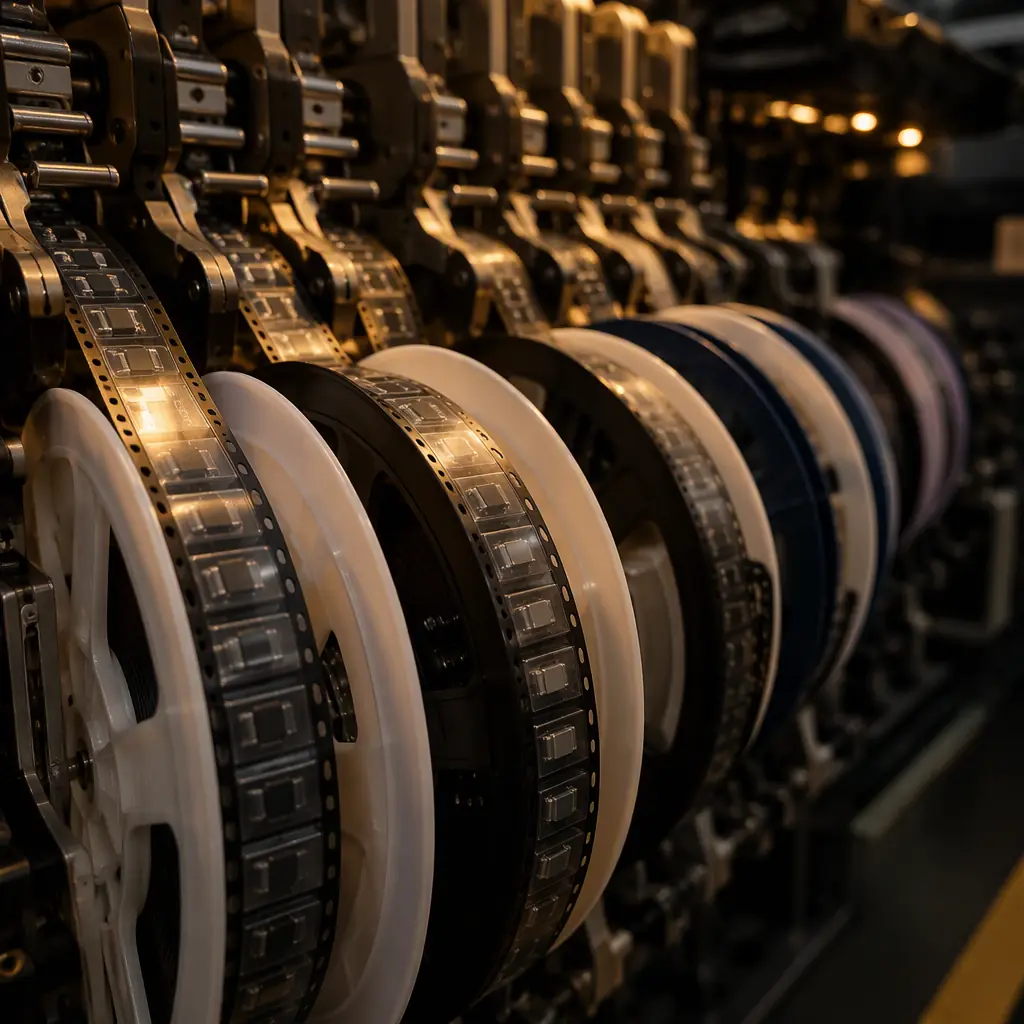
Tape-and-Reel Handling: Splicing, Cover-Tape Peel Force & Moisture
Behind every tape feeder is a reel, and how that reel is handled has a direct line to defect rate. Three aspects are worth a buyer's attention because they are invisible in a machine spec sheet and visible in a yield report.
Splicing. When a reel runs low mid-run, operators splice the new reel to the tail of the old. A poor splice — misaligned pockets, an extra-thick joint, tape that separates at the wrong place — produces a run of pick errors exactly at the splice point. Good practice is a splice made with the correct splice tape, checked before the line resumes, with the joint indexed past the feeder head. Every splice is a small window of elevated defect risk, which is why splice count per shift is a metric that correlates with placement quality.
Cover-tape peel force. The cover tape must peel with a consistent force — too high and the feeder stalls or the pocket lifts the component; too low and the tape opens early and parts escape. The peel characteristics of the tape are part of the component packaging spec, and mixing tape from different suppliers on the same feeder is a common and avoidable source of intermittent pick failures. A supplier that validates peel force on incoming reels is ahead of one that does not.
Moisture-sensitive devices. Parts with a moisture sensitivity level rating must be dry-baked and stored dry before they go on the line, and the floor-life clock runs from when they leave dry storage. Feeding a moisture-absorbed part through reflow produces the classic defects — popcorn cracking, delamination, internal voiding — that are then misattributed to the reflow profile. The handling discipline around moisture-sensitive feeders is a strong signal of process maturity; our guide to MSL and moisture sensitivity covers the control requirements in detail.
Procurement tip: Ask how many reel splices a typical run of your volume produces, and how incoming tape is checked. Splice points and mishandled moisture-sensitive reels are quiet defect generators that a capability datasheet never mentions.
The 7 Capability Questions to Ask in an SMT Audit
These are the questions that convert a vague "we have good machines" into an answer a buyer can act on. A supplier with real process control answers each one specifically; a supplier without it answers in generalities.
1. What placement Cpk does this line hold on a board family like mine, and how is it measured? The answer should name the component type, the pad geometry and the measurement method — not a single machine-sheet figure.
2. Which feeders are on the line for my part mix, and how many positions are electric versus mechanical? The answer tells you how much of your build will run at repeatable pick accuracy.
3. How is tape-and-reel incoming quality verified — peel force, pocket condition, splice procedure? A supplier with a documented incoming-tape check has closed a common defect route.
4. How are moisture-sensitive devices tracked from dry storage to the line, and what is the floor-life limit? The answer should reference a bake and floor-life log, not a policy statement.
5. What is the first-article verification process before a run, and does it check placement against pad tolerance? This connects the machine to the pad design; it is where a placement problem is caught before volume.
6. How does placement feed back into first-pass yield reporting? A supplier that cannot link placement to its FPY data is not closing the loop between equipment and defects.
7. What nozzle inventory exists for my component set, and how are nozzles validated? Fine-pitch and odd-form parts need the right nozzle; a missing nozzle becomes a manual placement, which becomes a defect risk.
High-Mix, Low-Volume: Where Changeover Replaces Speed
For a large share of B2B buyers — the ones placing prototype and small-batch orders before a volume commitment — machine speed is almost irrelevant and changeover discipline is decisive. A line that changes over in two hours and validates the setup will beat a faster line that changes over in eight and runs the first articles on faith.
The elements that determine high-mix placement quality are feeder setup consistency, nozzle availability, and the verification step between setup and run. The programming that defines the placement positions has to be checked against the physical board, and the first article has to be inspected against the pad tolerance before volume begins. Our guide to SMT line capacity and throughput treats changeover as a throughput variable; here the point is that it is also a quality variable, because a rushed changeover is where the first defects are born.
When to Specify Finer Pitch — and When the Board Should Move First
Buyers sometimes push for tighter placement capability to accommodate a design with very fine pitch or dense routing, when the better answer is to adjust the board. Before paying for placement capability the design does not need, it is worth asking whether the layout could relax the requirement: moving to slightly larger pads within the component's recommended land pattern, spreading components to reduce shadowing and access pressure, or choosing a package that a standard line places comfortably.
The tolerances that govern this sit alongside the fabricator's own capability limits — our guide to PCB manufacturing tolerances describes the etch, drill and registration limits that a design must respect — and the placement side is the mirror image of those. When a design and a line are matched deliberately, placement stops being a risk and becomes routine.
Summary: Capability Is a Per-Board Number, Not a Brand
Pick-and-place machine capability is not the machine brand, not the datasheet accuracy figure, and not the placement rate. It is the Cpk the line holds on a board family like yours, the feeders that present your parts, and the tape-and-reel handling behind them — splicing, cover-tape peel and moisture control. A buyer who asks about capability in those terms gets an answer that predicts yield; a buyer who asks about brand gets a sentence that predicts nothing. The seven questions above are the shortest path between the two.
At Huaxing PCBA we qualify placement per board family across 8 SMT lines under IATF 16949 and ISO 9001, run electric feeders with validated incoming tape on high-mix work, and track moisture-sensitive devices from dry storage to the line. Tell us your component mix and pitch and we will tell you which line and which feeder setup it will run on — no capability claims without the board. Send your Gerber and BOM and we will return a quote with the placement approach inside 24 hours, or talk to our process engineering team about a capability question you are working through.
