
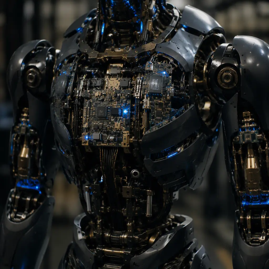
A humanoid robot is the most PCB-dense machine most hardware teams will ever build. Where an industrial arm might drive six joints, a humanoid drives sixty or more: each one a three-phase brushless motor with a gate driver, current sensing, an encoder, and a thermal constraint. The difference between a humanoid that walks and a humanoid that lurches is rarely the code. It is whether the control board stack can move 50 A of peak current into a joint, read its position at 1 kHz, and survive the vibration of a loaded knee, all inside a package that fits inside a leg joint.
This is why the PCB design question for a humanoid is not “what board do we use” but “how do we split one real-time control problem across a sprawling, multi-hundred-watt, multi-node printed circuit fleet.” At Huaxing PCBA we build boards at the 32-layer HDI tier down to 3/3 mil trace and 0.075 mm laser via capability, across 8 SMT lines and 4 DIP lines . The density and fidelity this platform demands. The structure below is the framework we use to evaluate a humanoid PCB design with customers.
Why a Humanoid Stresses PCBs Harder Than Any Other Robot Class
It is tempting to treat a humanoid as a scaled-up AGV or a cluster of cobots. It is not. Three properties make it a distinct PCB problem:
Joint count and its thermal multiplier
Sixty joints is not six joints times ten. Each joint is a full power block: gate driver, MOSFETs, a shunt or Hall current sensor, a resolver or encoder interface, and a local MCU or a CAN/SPI bridge. With a 10 W average per joint and a 200 W transient load shared across the platform, the aggregate power density in the legs is hostile to a standard FR-4 stackup.
Real-time, hard-latency control
A lower-limb joint must close a torque or position loop every millisecond, and the whole platform must reconcile those loops on a shared axis. That time budget is unchanged by adding joints. So the bus architecture and the on-board data path, not raw compute, are the bottleneck.
Gravity and the failure of the safe state
A humanoid cannot simply “release” to stop. If power is cut, the machine falls. That makes redundancy and a defined de-energized safe state a structural requirement of the board design, not a feature, and it drives the functional-safety workload documented in our ISO 26262 functional safety guide.
Key Takeaway: Treat a humanoid as a distributed real-time power-and-sensing system, not a robot. Every joint board, the compute board and the bus interconnects solve one shared control problem, so they must be designed as a fleet, not as independent boards bolted together.
The Control Architecture: Central Compute Plus Distributed Joint Drivers
Two viable topologies dominate, and the choice changes the board count, the bus and the failure story.
| Approach | Board structure | Bus | Pros | Cons |
|---|---|---|---|---|
| Central compute | 1-2 high-layer motherboards + many thin joint boards | High-speed Ethernet or GMSL | Frees the joints; single place for ML perception | One compute failure can be platform-wide; heavier cabling | Distributed | Many smarter joint boards, no large motherboard | CAN/CAN-FD or EtherCAT | Fault-local; scales; low point of failure | Harder synchronization; more ADC/loop work on each node | Hybrid | Central brain + meshed joint nodes | EtherCAT + CAN | Best of both; common in shipping humanoids | Most complex bus to bring up |
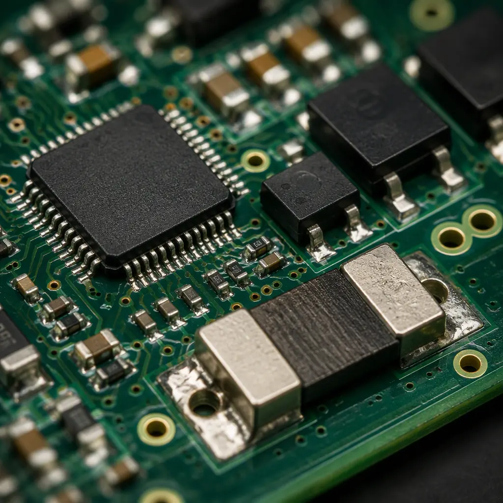
The hybrid approach is where most modern platforms land: a central high-layer compute board running perception and whole-body planning, with a meshed set of joint boards over a deterministic field bus. That split places different demands on the two PCB tiers, the compute board wants high layer count and controlled impedance across its whole plane, while the joint boards want high-current, low-inductance power routing in the smallest possible footprint. For a full read on routing discipline for the fast links, see our PCB signal integrity guide.
Joint Actuator Board Design: The Power Block
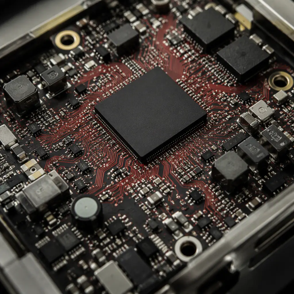
The joint board is where most humanoid PCB failures originate. It is simultaneously a 48 V to 800 V-class power stage, a precision sensing front-end, and a communications node. The design rules that matter:
Bus charge and decoupling close to the half-bridge
A block of a few hundred nanohenries of loop inductance between the DC bus and the MOSFET half-bridge turns into a big, hot ringing waveform. Place bus capacitors and the gate driver as close to the power stage as the mechanical envelope allows, and budget the loop-inductance path explicitly, the same discipline our SiC & GaN wide-bandgap guide lays out for 800 V traction.
Current sensing: shunt vs Hall vs the flux-gate corner
For a control loop you need a wide-bandwidth, low-latency current reading. Inline shunt with an isolated amplifier is the default for cost and speed; Hall sensors handle the high-current, galvanically-isolated corner; flux-gate sits in between for accuracy. The trace routing of the Kelvin sense pair defines how much error you get.
Gate-driver isolation and the return path
On a multi-joint platform where each joint is at a different potential, gate-driver isolation and a clean, single-point return path prevent circulating currents that look exactly like a torque error. This is a layout-class defect, not a software one.
Engineering Tip: Specify the peak-current point, the measurement bandwidth and the allowed loop inductance before you lay out a joint board. Those three numbers decide whether the MOSFETs, the sense method and the decoupling can ever work together.
Sensor Fusion: Encoders, IMU, Force-Torque and Time
A humanoid is a feedback machine. Each joint needs a position reading, and each part of the body needs a motion reading, fused at a common clock. That wiring is where a humanoid PCB design quietly goes wrong:
Signal integrity on the fast sensor links
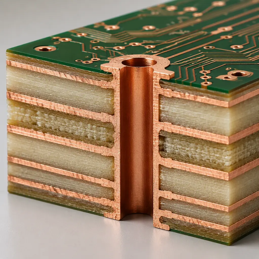
Encoders and IMUs are small but fast, and the differential pairs that carry them are easily corrupted by the commutation current running a few millimetres away. Route differential pairs over a continuous reference plane, back-drill the vias, and keep them away from the switching node.
Timing discipline across nodes
If the ankle IMU and the hip encoder are on different boards, their samples must carry a consistent timestamp or the whole-body controller sees a phantom oscillation. Design the timestamp distribution (PTP/SoE or a dedicated sync line) into the bus from the start.
Force-torque and tactile wiring
A foot with force sensing and a hand with tactile sensing add more sensor channels plus analog front-ends. Route analog traces away from the switching stage, use a quiet analog ground, and keep gain-setting components tight to the ADC.
For the differential-pair and clock discipline these boards demand at speed, our trace width & current capacity guide and the impedance control reference are the right starting points.
Reliability, Redundancy and the Safe State
Because a humanoid can hurt itself and its operator, redundancy is a design requirement. Two independent safety channels, a sensor and an actuation path that can each bring the platform to a controlled safe state, are the practical baseline. That means duplicated power rails on critical joints, cross-monitoring, and watchdog logic that defaults to a defined run-down rather than a hard cut. The functional-safety framework in our IEC 61508 article maps directly onto the SIL targets a humanoid vendor usually quotes.
Procurement Tip: Ask a humanoid hardware supplier three questions: how is the safe de-energized state implemented, are safety sensors and actuation on independent channels, and what is the documented MTBF of the joint power stage. A supplier that cannot answer all three has not engineered the board for the failure case.
Material, Thermal and Environmental Choices That Differ
The power density in the legs reshapes the material and thermal decisions:
High-Tg FR-4 and thick copper where the current lives
For the high-current joints, move to high-Tg FR-4 and 2 oz+ copper on the power planes; our copper weight guide and thermal management design guide cover the trade-off. For stiff, load-bearing segments, consider metal-core or a rigid-flex hybrid so the board is also part of the structure.
Rigid-flex for the limbs
The wrist, ankle and hip segments bend with the joint, and a hard board will crack. A rigid-flex limb board carries the continuity through the articulation. Our rigid-flex PCB guide details the bend-radius and stackup rules.
Sealing and potting
Sweat, dust and washdown are real in a humanoid deployed outside the lab. Conformal coating or potting at the joints, plus moisture-controlled packaging, protects the board, the acceptance details are in our conformal coating guide.
Summary: The Humanoid PCB Fleet Is Won at the Power Stage
Every humanoid PCB decision, the layer count on the compute board, the power-starved joint board, the rigid-flex in the limb, the redundant safety rail, supports the same goal: drive sixty joints at near-zero latency without a single point of failure that dumps the platform. Get the power stage and the signal routing right and the firmware has a chance; get them wrong and no amount of control code will keep the machine upright.
At Huaxing PCBA we build the tier of boards this needs, up to 32 layers, 3/3 mil trace, 0.075 mm laser vias, ±5% impedance, any-layer HDI, across 8 SMT lines in a 15,000 m² facility processing 8 million placements per day for 30+ countries, under ISO 9001, IATF 16949 and UL. Upload your humanoid control stack for a free DFM review, or talk to our engineering team about your joint-driver and compute-board specification.
