
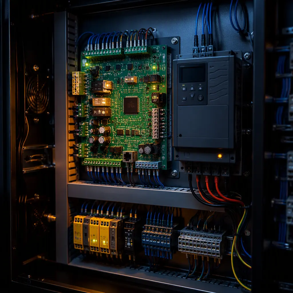
A modern elevator runs on a small network of printed circuit boards: a main control board that sequences the car, a variable frequency drive (VFD) board that moves the motor, door operator boards that open and close the cab, and safety boards that monitor the brake, governor and limit switches. Each one must operate for 10–20 years in a machine room or shaft that can swing from −10°C to +55°C, under voltage surges from motor starts, and under continuous vibration. When a board fails, the elevator stops. And in a 20-floor building, that means stairs for hundreds of people until the service technician arrives.
For elevator OEMs and component buyers, the PCB is the highest-risk purchased part in the control cabinet. A bad batch of boards discovered after installation triggers site visits, retrofit programs and liability exposure that dwarfs the component cost. This guide covers what to specify in elevator control PCBs, safety circuit architecture, drive board thermal design, communication interfaces and the manufacturing controls that make boards reliable for decades. Huaxing PCBA has assembled control electronics for lift systems under IPC Class 3 programs since 2015, including safety-rated boards for export to EU and Middle East markets.
What Makes an Elevator Control PCB Different From General Industrial Control
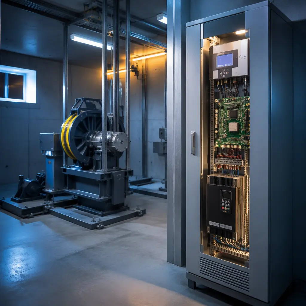
Elevator boards sit in a regulatory environment that most electronics never touch. The control system is a safety function under EN 81-20/50 (the European lift standard, adopted across the EU, Middle East and much of Asia), which means the PCB is part of a certified safety chain. Design decisions that are "nice to have" in a pump controller are mandatory in an elevator: physical separation of safety circuits, creepage distances that survive humidity, and trace widths that carry brake current without a single point of failure.
Safety circuits must be physically segregated
EN 81-20 requires that safety functions (overspeed governor, limit switches, brake contactors, door lock contacts) form a hard-wired safety chain that operates independently of the microprocessor. On the PCB, this means the safety relay logic occupies a separate zone with ≥8mm creepage isolation from logic circuitry, its own power input, and traces sized for the full contactor coil current. A common failure in imported boards: safety traces routed through the main processor's ground plane, which converts a CPU fault into a safety system failure.
The board must survive decades of thermal cycling
An elevator starts and stops hundreds of times per day. Each start heats the drive board's power section; each idle period cools it. Over 20 years that is hundreds of thousands of thermal cycles, and solder joints, not components, are what fail first. Boards built to IPC Class 3 with 2oz+ copper on power traces, high-Tg FR-4 (170°C Tg) and proper thermal reliefs routinely outlast boards built to commercial standards by a factor of three in accelerated thermal cycle testing.
EMC immunity is a certification gate, not a preference
EN 12015/12016 (electromagnetic compatibility for lifts) sets immunity levels far above typical industrial equipment: electrostatic discharge to 8kV contact, radiated immunity to 10 V/m, and fast transients on all power and signal ports. The machine room is electrically hostile, VFD switching at 4–16 kHz injects common-mode noise into every cable. Elevator boards need TVS arrays on every connector, ferrite-filtered power inputs, and a ground plane strategy that keeps the safety zone noise-free. Our EMC/EMI design guide details the protection topology.
Key Takeaway: Treat the elevator control PCB as a safety-certified component, not a commodity board. Creepage, trace sizing and EMC immunity are certification gates. Verify them at the design stage, because retrofitting them after field failures is 100x more expensive.
VFD Drive Boards: The Thermal and Current Challenge
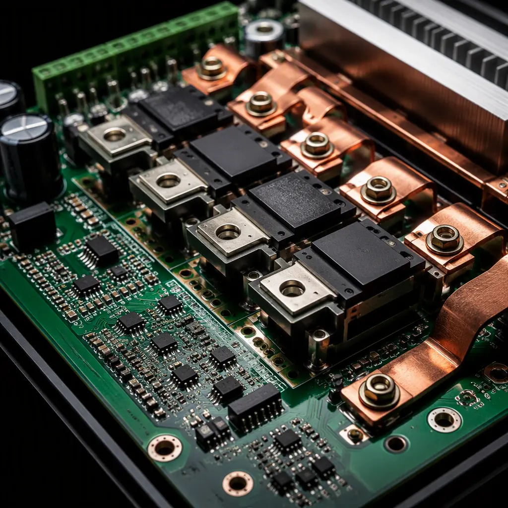
The drive board converts the mains supply to variable frequency power for the traction motor. In a typical 10-person elevator that means 5.5–15 kW output, with peak currents of 40–80A during acceleration. The PCB carries IGBT or IPM modules, gate drivers, DC bus capacitors and the current sensing chain, all in a board area of roughly 200×250mm.
Copper weight and thermal vias carry the current
Drive boards for 7.5kW+ elevators use 3oz–6oz copper on the power layers. A 6oz trace (210µm) at 4mm width carries about 60A continuous with a 20°C temperature rise per IPC-2221. But the real thermal path is the array of 0.3mm thermal vias under the IGBT module, transferring heat to the heatsink plane on the back of the board. Specify stitched via arrays with 1.0–1.2mm pitch across the entire module footprint; missing vias are the leading cause of premature drive board failure.
Gate drive and sensing must stay clean
The gate driver section switches IGBTs in under 1µs, generating di/dt transients that corrupt weak analog signals. Keep gate resistors within 5mm of the module pins, route the DC bus sense traces as a Kelvin pair to the shunt, and never route the isolated gate supply return through the logic ground. A 1% current sense error translates directly to torque ripple, passengers feel it as vibration. Our power electronics PCB guide covers the layout rules in depth.
DC bus and braking resistor circuits
When the car decelerates, the motor regenerates power back into the DC bus, raising bus voltage. The drive must dump that energy through a braking chopper into a resistor bank. The chopper circuit on the PCB sees 600–800V DC bus voltage (for 400V mains), specify ≥2.5mm clearance between bus traces, conformal coating rated for high voltage, and solder mask with adequate dielectric strength. See our high-voltage PCB design guide for creepage and clearance tables.
Door Operator and Car Control Boards
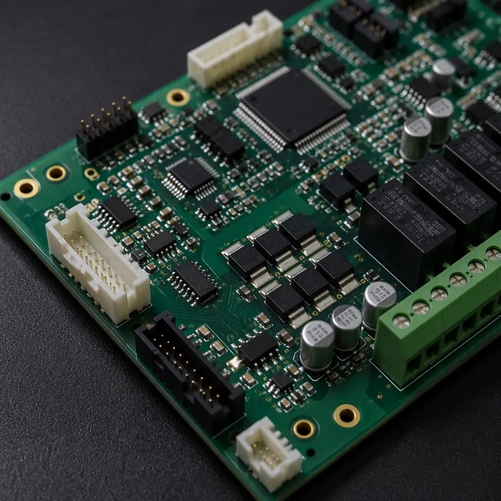
The door operator board is the highest-cycle board in the elevator: it runs every door open and close, 200–400 cycles per day, with the motor reversing direction on every cycle. Door boards typically integrate the motor drive (often a small BLDC or DC motor), encoder feedback, obstruction detection and the door lock relay interface.
Position sensing must be absolute and redundant
Door boards rely on hall sensors or encoders to know the door position every millisecond. Specify redundant sensing (two channels, quadrature) so a single sensor failure triggers a controlled stop rather than a door that slams. The sensor inputs need RC filtering and TVS protection because the door frame wiring acts as an antenna for motor noise.
Door lock monitoring is part of the safety chain
The door lock contact is a safety device: the elevator must not move unless the locks are proven closed. On the PCB, the lock monitoring circuit (typically 24V DC wetting through the lock contacts) must be electrically isolated from the door motor drive, with optocoupler feedback to the controller. Trace spacing between the 24V lock circuit and logic must meet the same creepage rules as the main safety chain.
CANopen Lift Bus and Communication Interfaces
Modern elevator systems communicate over a CANopen lift profile (CiA 417), linking the car control board, shaft boards, door boards and floor position indicators on a 2-wire bus running up the shaft. The bus can span 100+ meters with 30–60 nodes, and it shares the shaft with motor cables, an EMI nightmare.
Bus termination and protection
Each node board must include the 120Ω termination option, common-mode choke on the bus lines, and TVS clamps at the connector. Our RS-485 design guide applies the same topology principles. Differential pairs, stub-free drop connections and transceiver protection are what keep a 100m bus alive in a shaft full of VFD noise.
Isolated power for shaft nodes
Floor position boards and shaft safety boards sit on different grounds than the machine room controller. Specify isolated DC-DC converters (or optocoupler + isolated transceivers) on every node so ground potential differences, which can exceed 5V between floors in old buildings, never translate into bus current. Non-isolated nodes are the most common field failure in retrofitted CAN lift systems.
Manufacturing Controls That Matter for Elevator Boards
Elevator boards fail in the field for manufacturing reasons at least as often as design reasons. The factory controls below are what separate a 20-year board from a 2-year board, and they should be written into your supplier agreement.
| Control | Elevator-grade requirement | Commercial default |
|---|---|---|
| Solder joint inspection | 100% AOI + X-ray on BGA/IGBT pads | AOI only, sampling |
| Cleanliness | Ionic contamination <1.56µg/cm² (ROSE) | Visual check |
| Conformal coating | 2-coat, 50–75µm, full UV inspection | Single coat, spot check |
| Burn-in | 48h at 60°C with power cycling | None or 4h |
| Traceability | Full lot traceability to components | Date code only |
Conformal coating deserves special attention: elevator machine rooms in humid climates (or shafts near washing stations in some buildings) expose boards to condensation. A double-coated board with acrylic or silicone conformal coating at 50–75µm withstands the salt-laden, humid environments typical of coastal installations far better than uncoated boards. Specify the coating thickness in your IPC-A-610 acceptance criteria, it is a measurable, inspectable requirement.
Traceability from board to building
When a lift OEM issues a recall or retrofit notice, they need to know which boards went to which site. Specify IPC-1782 lot traceability: every board marked with a serial number, manufacturing lot recorded against component date codes, and test data archived for 10+ years. This is standard practice for elevator-tier suppliers and non-negotiable for export programs.
Specifying Your Elevator PCB Program
Write the specification before you send RFQs. A complete elevator board specification includes: the safety circuit zoning requirement, copper weight per layer, thermal via arrays, creepage and clearance values for each voltage domain, EMC immunity test levels (EN 12015/12016), conformal coating thickness, burn-in duration, and the acceptance criteria (IPC-A-610 Class 3). The PCB specification and RFQ guide provides a template you can adapt, and the incoming inspection guide shows what to verify when boards arrive.
Huaxing PCBA manufactures elevator and escalator control electronics under IPC Class 2 and Class 3 programs, with 3oz–6oz copper capability, double-coat conformal coating lines, 48-hour burn-in racks and full lot traceability across 8 SMT lines. Read our testing methods guide to see how AOI, X-ray and functional test are applied, or send your design files for a DFM review and a manufacturing quote within 24 hours.
