

The commercial building automation market — encompassing HVAC controllers, lighting management, access control panels, and BMS (Building Management System) gateways — is forecast to reach $155 billion by 2028. Every smart building deploys hundreds of controller PCBs across its floors: VAV box controllers in ceiling plenums, thermostat boards on every wall, chiller plant controllers in mechanical rooms, and BACnet/IP gateways in IT closets. A single failed controller PCB in a 50-story office tower can disable an entire floor's HVAC — triggering tenant complaints and a $500+ emergency service call.
At Huaxing PCBA, we manufacture building automation PCBs for OEMs serving commercial, institutional, and industrial facilities across 18 countries. Our production line is qualified for the full stack: 2-layer to 8-layer controller boards, mixed through-hole and SMT assembly (many building automation products still use DIP-packaged RS-485 transceivers and terminal block connectors), conformal coating for plenum-rated installations, and 100% ICT or flying probe test with relay and optocoupler functional verification. If you're designing a building controller, here's how to specify the PCB manufacturing so it survives a decade in the ceiling.
What Makes Building Automation PCBs Different from General Industrial Control
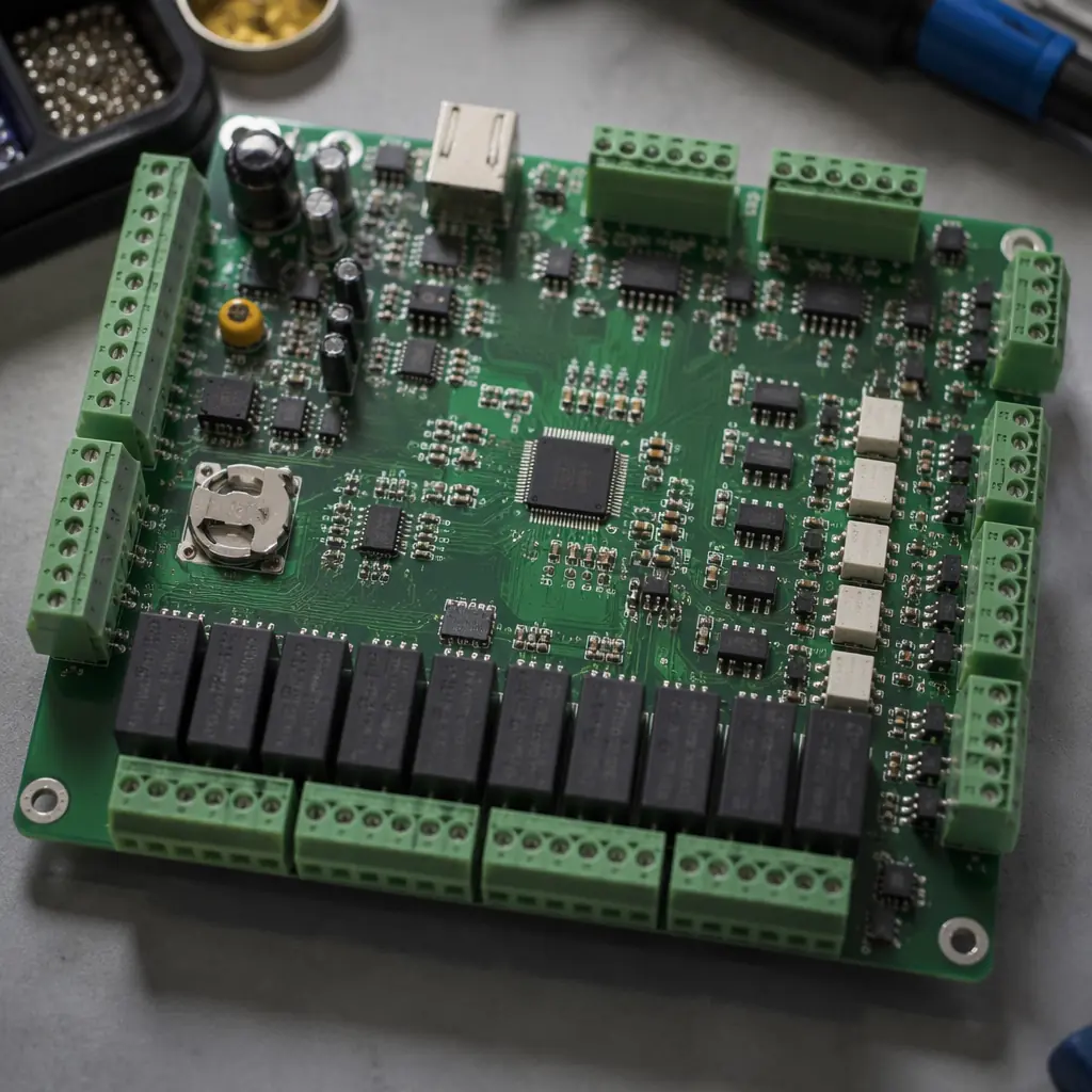
Building automation PCBs sit in a unique operating environment that's less extreme than factory-floor industrial control but more punishing than indoor consumer electronics. The board lives in a metal enclosure mounted above a ceiling tile or inside a mechanical room — where ambient temperature swings from 5°C (winter night with HVAC off) to 55°C (summer afternoon with chiller heat rejection), humidity cycles from 20% to 95% RH, and 24/7/365 operation means zero scheduled downtime.
Mixed Through-Hole and SMT Assembly: Industry-Standard Connectors Still Use DIP Packages
Unlike consumer electronics that are 100% SMT, building automation PCBs typically have 15-30% through-hole components: pluggable terminal blocks (Phoenix Contact, Weidmüller), DIP-packaged RS-485 transceivers (MAX485, SN65HVD08), and through-hole relays (Omron G5, Panasonic JS series). This hybrid assembly process needs careful sequencing — wave solder the through-hole components after SMT reflow, or use selective soldering for mixed-technology boards. Our wave vs selective soldering guide compares the two approaches for mixed-technology designs.
24V AC/DC Power Supply Section: High-Current Traces and Thermal Management
Almost all building automation controllers are powered by 24V AC (from a Class 2 transformer) or 24V DC. The power supply section rectifies 24V AC to regulated 3.3V and 5V DC rails, with the rectifier diodes and linear regulator generating 2-4W of continuous heat inside a sealed plastic enclosure. The PCB must use 2 oz copper on the power plane with thermal vias stitching under the regulator's exposed pad to the bottom-layer copper pour — otherwise, the junction temperature exceeds 125°C and the regulator enters thermal shutdown. Our thermal management guide covers the layout strategies for power-dense sections.
RS-485 Multi-Drop Bus: ±15kV ESD Protection on Every Node
Building automation networks (BACnet MS/TP, Modbus RTU) use RS-485 multi-drop buses that can span 1,200 meters across an entire building. Every controller PCB on the bus is a potential entry point for ESD strikes (personnel walking across carpeted office floors) and induced transients from nearby motor starts (elevators, pump VFDs). The RS-485 transceiver must be protected with TVS diodes (SMBJ series, 600W peak pulse power) placed within 10mm of the connector pins, and the PCB ground plane must provide a low-impedance path to the chassis ground via a dedicated earth terminal. See our EMC/EMI design guide for the protection layout rules.
Relay Outputs: Creepage and Clearance for 277V AC Loads
Building controllers switch real loads — fan motors, damper actuators, electric heaters at 120V or 277V AC. The PCB traces between the relay contacts and the output terminal blocks must maintain 6.4mm creepage and 4.0mm clearance (per IEC 60335-1 for reinforced insulation at 250V working voltage). Additionally, the relay coil flyback diode and snubber network (for inductive loads) must be placed close to the relay to minimize the loop area that radiates EMI. For high-current loads above 5A, use 3 oz copper on the relay output traces. Our copper weight selection guide covers the trace width calculator for every current level.
10-Year Lifecycle: Component Obsolescence Planning from Day One
Commercial buildings have 30-50 year lifetimes, and the BMS controllers are expected to operate for at least 10-15 years before retrofit. This means the PCB design must avoid single-source components with short lifecycles — especially the microcontroller and the communication PHY. Specify industrial-temperature-range ICs (-40°C to +85°C) even if the ambient spec is 0°C to 50°C; the extra margin eliminates infant mortality from thermal cycling. Our component obsolescence guide explains the EOL risk assessment framework we use in DFM reviews.
BMS Gateway and IP Controller PCBs: The Data Aggregation Layer
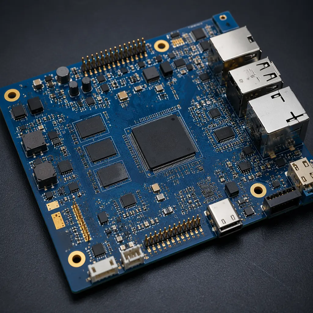
At the top of the building automation hierarchy sit BMS gateways and IP controllers — devices that aggregate data from dozens of field-level RS-485 controllers and expose it via BACnet/IP, MQTT, or a REST API to the building operator's dashboard. These gateways use more complex PCBs: typically 6-8 layers with an applications processor (ARM Cortex-A series or x86), DDR memory, eMMC storage, dual Ethernet with 802.3at PoE, and sometimes an LTE modem for remote monitoring of unmanned facilities.
| Parameter | Field Controller PCB | BMS Gateway PCB | Touch Panel / Thermostat PCB |
|---|---|---|---|
| Layer count | 2-4 layers | 6-8 layers | 4-6 layers |
| Processor | Cortex-M4 @ 120 MHz | Cortex-A7/A53 @ 800 MHz+ | Cortex-M7 @ 400 MHz |
| Memory | 512KB-1MB SRAM | 512MB-1GB DDR3/DDR4 | 8-32MB SDRAM |
| Interfaces | RS-485 × 2, 4-20mA × 4 | 2× Ethernet, USB, RS-485, LTE | LVDS display, touch, RS-485 |
| Power consumption | 2-4W | 8-15W | 3-6W |
| PCB size (typical) | 100 × 70mm | 140 × 100mm | 120 × 80mm |
For BMS gateway PCBs, the DDR routing is the most critical layout task — a 16-bit DDR3 interface at 533 MHz requires length matching within ±25 mils across all data byte lanes, controlled impedance at 40Ω single-ended, and a solid reference plane with no splits under the routing. Any impedance discontinuity causes timing violations that manifest as intermittent system crashes, not clean failures. Our impedance control guide covers the fabrication specification for DDR routing, and our stackup design guide walks through the layer assignment for a 6-layer DDR PCB.
Key Takeaway: The most common field failure in building automation PCBs is not a semiconductor defect — it's a connector-related issue: loose terminal block screws causing intermittent 24V power, oxidized RS-485 connector pins increasing bus errors, or relay contact welding from an inductive load without a snubber. The PCB must be designed so that connector failures fail safely: include a watchdog timer that reboots the MCU if the RS-485 bus goes silent for > 5 seconds, and add a 500mA PTC fuse on the 24V input to protect against field wiring shorts.
How to Specify Building Automation PCBs: 7 Requirements for Your Fabrication Drawing
Laminate: FR-4 Tg 150°C Minimum, CTI ≥ 175V for Relay Boards
Standard FR-4 with Tg 150°C is sufficient for most building automation applications (ambient ≤ 55°C). However, for controller boards with relay outputs switching 277V AC, specify a laminate with CTI (Comparative Tracking Index) ≥ 175V — this reduces the risk of carbon tracking across the PCB surface between relay terminals over years of operation in humid environments. Full laminate comparison here.
Surface Finish: HASL Lead-Free for Field Controllers, ENIG for Gateway Boards
HASL (lead-free) provides the best solderability for through-hole terminal blocks and relay pins — the thicker solder coating survives multiple thermal cycles of screw-terminal torque. For BMS gateways with fine-pitch BGA processors and DDR memory, switch to ENIG for flatness. Our HASL vs ENIG guide covers cost and reliability tradeoffs.
Conformal Coating: Acrylic for Plenum-Rated Installations
Any PCB installed in a ceiling plenum (VAV controllers, damper actuators, lighting controllers) must use conformal coating to prevent dust accumulation and condensation — both are unavoidable in plenum spaces. Apply 25-50μm acrylic (IPC-CC-830 Type AR) with masked connectors and programming headers. Coating selection guide here.
Silkscreen: Full Component Designators and Polarity Marks
Building automation PCBs are serviced by HVAC technicians in the field — not electronics engineers in a lab. The silkscreen must clearly mark every terminal block function (24V, GND, A, B, AOUT1, AOUT2), every relay's NO/COM/NC contacts, and every LED's function (PWR, TX, RX, FLT). This reduces field wiring errors and service callbacks by 40-60% according to our OEM customers' field data.
Fuse Protection: PTC Resettable Fuse on 24V Input and Each Relay Bank
A field wiring short on a 24V AC input can destroy the power supply section in under 5 seconds. We specify a 500mA-1A PTC resettable fuse (e.g., Littelfuse 1812L series) on the 24V input and a separate PTC on each bank of 4 relay outputs. The PTC must be placed before the bridge rectifier to protect the entire power chain. See our high-voltage design guide for protection circuit layout.
Firmware Update: SWD/JTAG Header with ESD Protection
Every building automation PCB should include a 10-pin Cortex debug header (SWD + UART) for field firmware updates — even if OTA updates are the primary method. Field technicians need a wired fallback when a controller's firmware is corrupted. Protect the SWD lines with low-capacitance TVS diodes (under 1pF) to avoid signal integrity issues at 10 MHz SWD clock speeds.
Traceability: QR Code with MAC Address and Serial Number
Building automation installers need to commission each controller onto the BACnet network by its MAC address or device instance number. A QR code on the PCB silkscreen (laser-marked, not inkjet — ink fades in plenum heat) containing the MAC address and serial number cuts commissioning time by 80% compared to manual entry. Include human-readable text beneath the QR code for installer fallback. Read our FAI guide for the documentation we include with every production batch.
The BACnet Compliance Test: Why Your PCB Quality Directly Affects Protocol Certification
BACnet certification (BTL listing) requires the controller to pass a conformance test at an authorized testing laboratory. What many OEMs discover too late is that PCB-level issues — not software bugs — are the most common cause of BACnet test failures: RS-485 signal reflections from incorrect termination resistor placement, ground loop noise from a split ground plane, or intermittent communication drops from a marginal solder joint on the transceiver IC.
At Huaxing PCBA, our building automation production experience includes 12+ OEMs whose products have achieved BTL certification. We understand that the RS-485 traces must be daisy-chained (not star-routed), that the 120Ω termination resistor must be switchable (jumper or DIP switch) and placed within 20mm of the connector, and that the RS-485 common (signal ground) must be connected to chassis earth through a 1MΩ resistor and 0.01μF capacitor in parallel to bleed common-mode voltage without creating ground loops. These are PCB layout details that software engineers never see — but they determine whether the BTL test passes. See our signal integrity guide for the differential routing rules that prevent RS-485 reflection issues.
Building Automation PCB Trends: Matter, Thread, and Wireless Retrofits
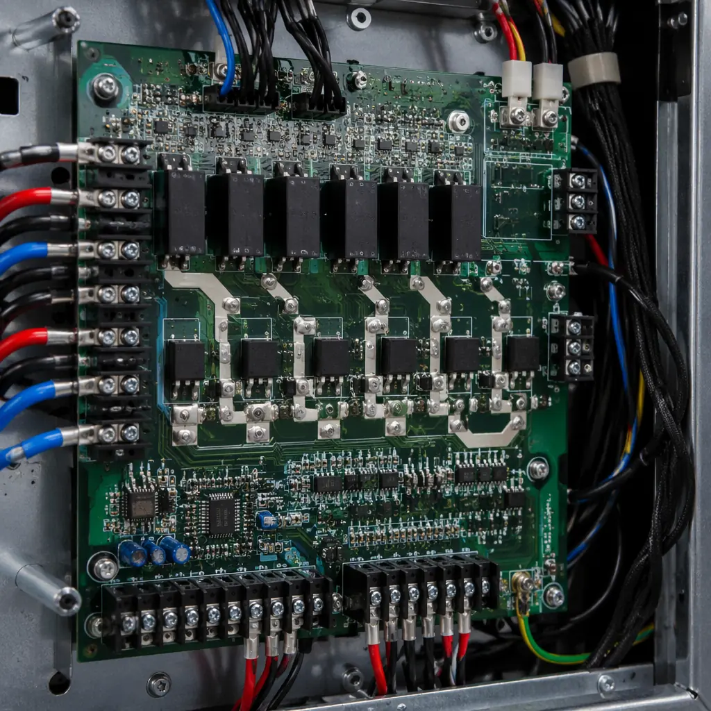
The building automation industry is moving toward wireless connectivity for retrofit applications — adding smart thermostats and occupancy sensors to existing buildings without pulling new RS-485 cable. Three wireless protocols are competing for this space:
Thread / Matter: The Matter smart home standard (backed by Apple, Google, Amazon) is extending into commercial buildings. Thread-based controllers use a 2.4 GHz 802.15.4 radio with an IPv6 mesh stack — the PCB needs a dedicated RF section with controlled-impedance antenna feed and ground-plane clearance under the antenna keep-out area. Our IoT PCB design guide covers the RF layout rules that apply to Thread designs.
LoRaWAN for Facility Monitoring: For campus-scale deployments (university, hospital, industrial park), LoRaWAN provides kilometer-range wireless at very low power. The 868/915 MHz LoRa radio on the PCB requires a 50Ω antenna trace and careful separation from noisy digital sections. See our RF PCB guide for the fabrication tolerance requirements.
BACnet/SC (Secure Connect): The new BACnet/SC standard replaces MS/TP's RS-485 with TLS-encrypted WebSocket over IP. This means the controller PCB now includes an Ethernet PHY (100BASE-TX) and a more powerful processor capable of TLS 1.3 handshakes — pushing the design from 2-layer to 4-layer and the MCU from Cortex-M4 to Cortex-M7 or Cortex-A.
Getting Started with Your Building Automation PCB Project
Building automation PCB manufacturing requires a partner who understands the industry's unique combination of legacy through-hole technology, 24/7 reliability requirements, and 10+ year product lifecycles. The right PCB manufacturer doesn't just fabricate your Gerber files — they review your design for the BTL certification pitfalls, the field-wiring failure modes, and the thermal hotspots that only appear after five summers in an Arizona mechanical room.
At Huaxing PCBA, we've manufactured building automation PCBs for over 8 years across OEMs serving the commercial, healthcare, education, and hospitality sectors. Our certifications (ISO 9001, IATF 16949, UL ZPMV2) and our in-house conformal coating line ensure your controllers meet the reliability expectations of building owners who expect them to run for a decade without a service call. See our full certifications, or send your Gerber files to our team for a 24-hour quote with free DFM review focused on building automation reliability requirements.
