
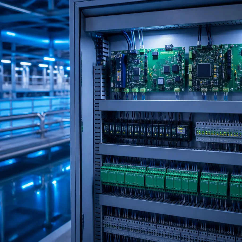
A water treatment plant runs on electronics that most people never see: remote terminal unit (RTU) boards that read pressure and flow sensors, pump controller boards that start and stop motors, chemical dosing boards that meter chlorine to within 0.1 ppm, and SCADA gateway boards that report everything back to the control room. These boards run 24 hours a day, 365 days a year, in enclosures that range from climate-controlled control rooms to dripping valve pits. A failed board in a treatment plant is not an inconvenience. In a regulated system it can mean a compliance violation or a supply interruption for thousands of connections.
For water industry OEMs, the PCB is where reliability and measurement accuracy are won or lost. This guide covers what to specify in water treatment control PCBs: analog front-end design for process sensors, pump drive and switching reliability, protection against humidity and aggressive chemicals, and the manufacturing controls that deliver boards with 20+ year service life. Huaxing PCBA has manufactured control electronics for water and wastewater projects since 2017, including RTU and dosing boards for export to the EU, Middle East and Southeast Asia.
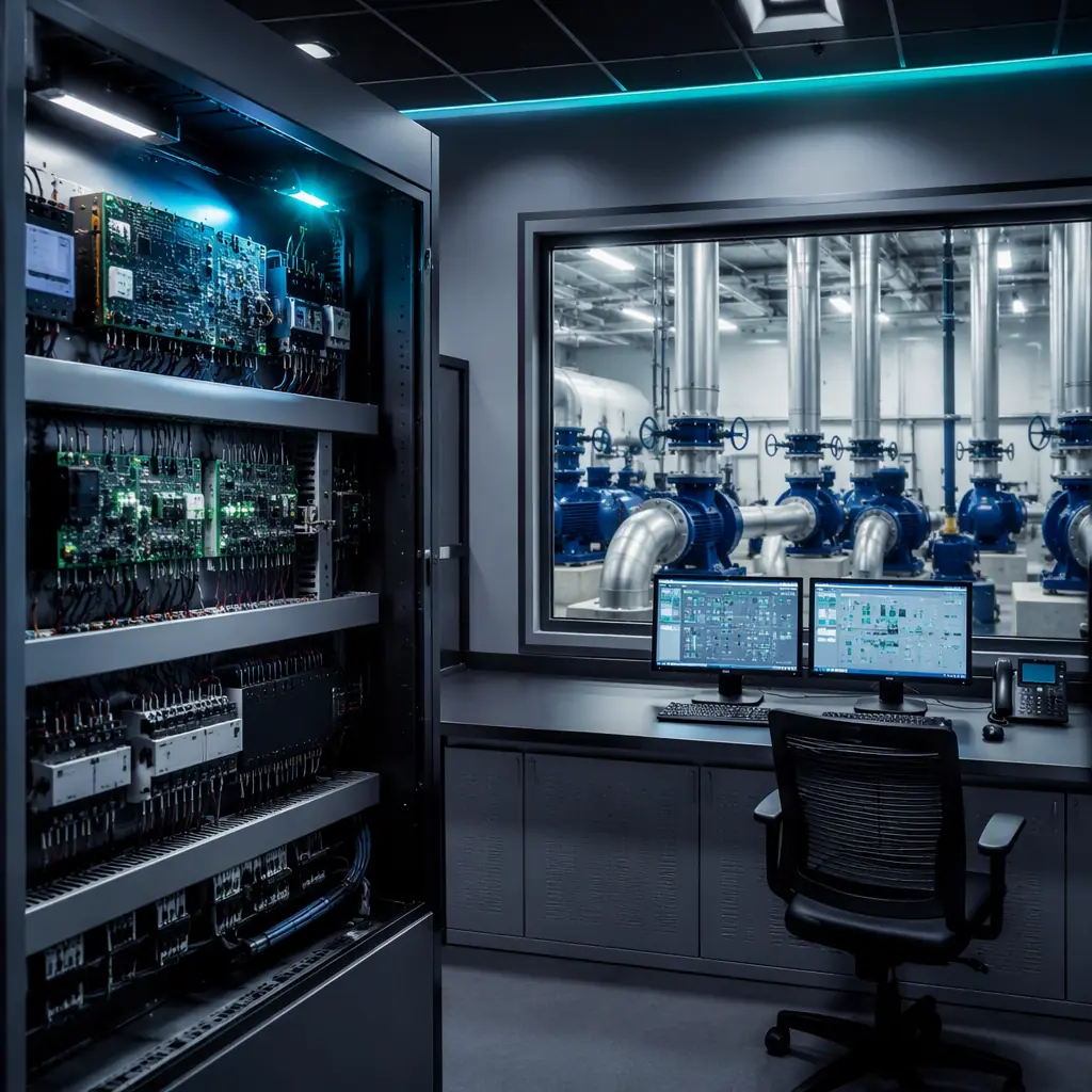
The Analog Front End: Where Measurement Accuracy Is Decided
Process control quality in a water plant depends on measurement accuracy. Flow, pressure, level, pH, chlorine and turbidity signals arrive at the control board as 4-20mA current loops (the process industry standard) or 0-10V signals. The analog front end, the circuit between the field wiring terminal and the ADC, determines whether that signal arrives at the processor intact.
4-20mA loop design: precision resistors and filtering
A 4-20mA loop converts to voltage across a precision burden resistor: typically 250Ω, giving 1-5V for the full scale. Use 0.1% tolerance, 25ppm/°C metal film resistors for the burden, and add a two-stage RC filter (e.g., 1kΩ + 100nF, cutoff ≈1.6kHz) before the ADC. A common field failure: boards built with 1% resistors drift enough across temperature that a chlorine reading shifts by 0.2 ppm, pushing dosing off-spec. Precision matters more than any other component decision in this circuit. Our mixed-signal PCB design guide covers the grounding strategy behind a clean analog front end.
Galvanic isolation between field and logic
Field wiring in a treatment plant runs alongside power cables and shares earth with motor circuits. Specify isolated analog inputs (isolated DC-DC + isolation amplifier, or isolated ADC) so ground loops and pump-start transients never corrupt measurements. Isolation rating should be ≥1500Vrms, the same class used in industrial control boards.
Surge protection on every field connection
Lightning-induced surges and pump motor transients enter through sensor cables. Every analog input needs a TVS clamp (e.g., SMBJ12A for 24V loops) plus series resistance, and the board should pass IEC 61000-4-5 surge testing at 1kV on signal ports. This is the difference between boards that survive storm season and boards that fail in waves.
Key Takeaway: In water treatment electronics, the analog front end is the product. Specify 0.1% precision burden resistors, galvanic isolation and surge protection on every field input. Measurement drift and ground-loop noise are the top field failure modes.
Pump and Valve Controller Boards: Switching Real Power
Pump controllers start motors from 0.75kW to 90kW+, either directly (DOL), via soft starter or via VFD. The controller board must handle the switching side, contactor/relay drive, status sensing, and protection interlocks, without letting motor transients destroy the logic.
Relay drive with flyback suppression
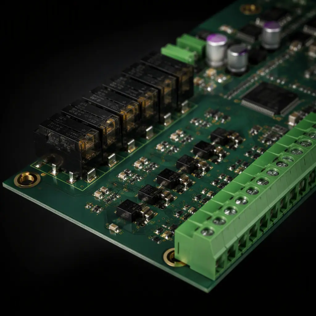
Contactors and relay coils are inductive loads. Every coil driver on the board needs a flyback diode (for DC coils) or RC snubber (for AC), placed within 10mm of the driver. Missing suppression is the single most common cause of "the board resets when the pump starts" field reports. Include a status feedback path so the controller can verify the contactor actually closed.
Motor protection interlocks
Good pump boards include dry-run protection (flow switch or current sensing), thermal overload input and phase-loss detection. The current sensing can be done with a current transformer feeding a precision rectifier to the ADC. Specify the sensing range to match the motor FLA so the board reads 10-100% load accurately. See our DFT guide for making these circuits testable in production.
Humidity, Chemicals and the IP-Rated Board
Water treatment environments are brutal for electronics: 90%+ relative humidity in valve pits, chlorine gas in dosing rooms, condensation on enclosures in the morning. Standard commercial boards fail in months. Boards built for this industry need environmental protection designed in from the start.
Conformal coating: the first line of defense
Specify acrylic or silicone conformal coating at 50-75µm on all boards exposed to humidity, with edge coverage verified by UV inspection. For chlorine-rich or corrosive atmospheres, silicone coating (or parylene for critical boards) outperforms acrylic significantly. Coating thickness is measurable, put it in the IPC-A-610 acceptance criteria.
Creepage and clearance for humid environments
At 90% RH, the effective creepage distance needed for a given voltage doubles or triples. For 24V circuits use ≥1.5mm creepage; for 230V mains-side circuits ≥6mm (pollution degree 3). If your board controls 400V pump circuits, follow the high-voltage PCB design rules . And verify the board passes IEC 61010 or UL 61010 spacing requirements for the target market.
Connector selection and sealing
Pluggable screw terminals with ≥7.5mm pitch, IP67-rated when mated, are the standard for plant I/O. Specify connectors with gold-plated contacts for low-level analog signals, tin contacts on 4-20mA inputs develop contact resistance that drifts with temperature. For boards that may see direct spray, consider potting or encapsulation of the entire assembly.
Communication: SCADA, Modbus and Remote Telemetry
Every control board in a modern plant talks to a SCADA system. The dominant field bus is RS-485 Modbus RTU, with Ethernet/Modbus TCP growing for new plants and cellular RTUs for remote sites.
RS-485 Modbus with full protection
Specify the transceiver with 120Ω termination option, common-mode choke, TVS protection and isolation. Field buses in plants span hundreds of meters and connect dozens of devices. A single unprotected node can take down the whole segment. Our RS-485 design guide covers termination and protection in detail.
Ethernet and cellular gateways
Newer RTUs integrate an Ethernet PHY or cellular modem. Ethernet magnetics must be specified with the right isolation rating, and cellular modules need their antenna feed and grounding handled per the module vendor's reference design, see our PCB antenna design guide for the layout rules that keep RF performance.
Manufacturing Controls for 20-Year Service Life
Water industry boards must outlast the plant's warranty period by a wide margin. The manufacturing program is where that longevity is built.
| Control | Water-treatment-grade requirement | Commercial default |
|---|---|---|
| PCB base material | High-Tg FR-4 (170°C), 2oz inner copper on power boards | Standard FR-4, 1oz |
| Solder joint inspection | 100% AOI + X-ray where applicable | AOI sampling |
| Cleanliness | Ionic contamination <1.56µg/cm² (ROSE) | Visual check |
| Coating | 2-coat conformal, 50-75µm, UV-inspected | None or single coat |
| Burn-in / test | 24-48h burn-in + functional test on every unit | Sampling only |
| Traceability | Lot traceability, test data archived | Date code |
Functional test matters especially for analog accuracy: every board should be tested against a calibrated 4-20mA source and the ADC readings verified to the specified accuracy (e.g., ±0.1% of span) before shipment. Boards that fail this test in the field cost a service visit; boards that fail it in the factory cost nothing. Our testing methods guide explains how AOI, ICT and functional test combine to catch process defects.
Specifying Your Water Treatment PCB Program
Write the full specification before RFQ: analog accuracy requirements per channel, isolation rating, surge test level, conformal coating type and thickness, connector types, burn-in duration and acceptance criteria. The PCB specification and RFQ guide gives you a template, and the incoming inspection guide shows what to verify on arrival.
Huaxing PCBA manufactures water treatment and industrial control electronics under IPC Class 2 and Class 3 programs, with double-coat conformal coating lines, calibrated analog functional test fixtures, 24-48h burn-in racks and full lot traceability across 8 SMT lines. Read our industrial control guide for the broader reliability picture, or send your design files for a DFM review and a manufacturing quote within 24 hours.
