
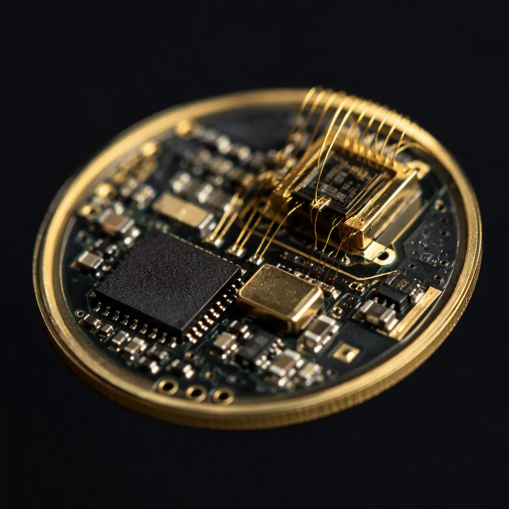
An implantable device is the most unforgiving environment in electronics. A pacemaker's electronics must run for 8–12 years on a single battery, inside a titanium case that never exceeds a few cubic centimetres, while the body attacks every material it touches, saline, enzymes, mechanical flexing with every heartbeat. The PCB at the centre of that system has none of the luxuries of a consumer board: no service access, no thermal relief, no second chance.
The implantable PCB category sits at the extreme end of medical electronics, distinct from the IPC Class 3 boards in hospital monitors and diagnostic equipment covered in our medical device PCB guide. This guide covers the design, material, manufacturing and qualification decisions for boards that will spend a decade inside a human body, and what a procurement team should verify before trusting a manufacturer with them.
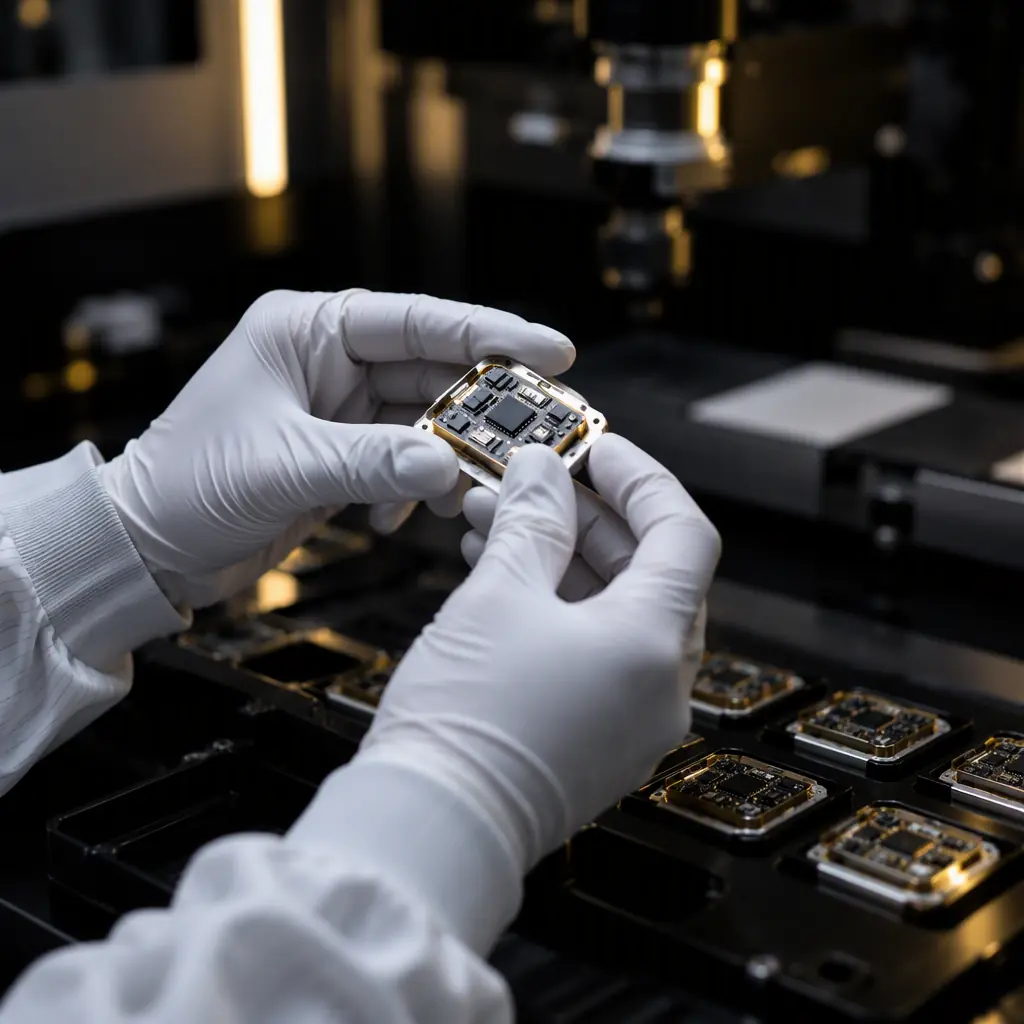
What Makes an Implantable Board Different
Three constraints separate implantable boards from every other medical PCB: size, reliability and biocompatibility. Each one reshapes the manufacturing process.
| Constraint | Typical Consumer Board | Implantable Board |
|---|---|---|
| Board area | 100–500 cm² | 1–10 cm² |
| Layers | 2–8 | 4–12, HDI microvia |
| Min trace/space | 4/4 mil | 2.5/2.5 mil or tighter |
| Component pitch | 0402 common | 0201 / 01005, bare die |
| Design life | 2–5 years | 8–15 years continuous |
| Failure tolerance | Field returns | Surgical revision |
Every dimension is pushed to the edge of what fabrication can hold. A pacemaker's hybrid board is typically 0.4–0.8 mm thick with blind and buried microvias, and the assembly uses wire bonding and flip-chip alongside the smallest SMT components available. The reliability requirement is the real driver: a single latent defect that escapes test can mean a second surgery for the patient, which is why implantable boards are built under process controls that go beyond ordinary Class 3.
Materials: Biocompatibility Is a System Property
Biocompatibility is not a single material property. It is a system-level behaviour that the PCB, the components, the solder and the housing all contribute to. The board itself is usually sealed inside a hermetic titanium or ceramic package, so the PCB materials rarely contact tissue directly. That changes the priority order.
High-reliability laminate with tight CTE control
The board must not outgas or leach ionic contamination into the hermetic cavity over a decade. Materials are selected for low ionic extractables, low moisture absorption and thermal stability through assembly. Polyimide and high-Tg FR-4 both appear in implantables; the choice follows the thermal and mechanical duty of the device. Laminate selection logic is covered in our PCB materials guide and laminate selection guide.
Ionic cleanliness, measured, not assumed
Residual flux and ionic contamination inside a hermetic package cause corrosion and dendritic growth over years. Implantable assemblies are cleaned to ionic levels far below commercial standards and verified with ionic contamination testing, the same measurement our ionic contamination guide explains, but with pass limits up to an order of magnitude stricter. Cleanliness is verified per lot, not per product release.
Solder and finish: no leachable metals
Even inside a hermetic package, finishes and solder alloys are chosen to avoid anything that could corrode or migrate under bias. Gold-based finishes (ENIG/ENEPIG) dominate because they are inert and flat for fine-pitch assembly; lead-free SAC solder is standard in most regions, with the joint quality verified by X-ray on every connection. Our surface finish guide and solderability testing guide cover the selection logic.
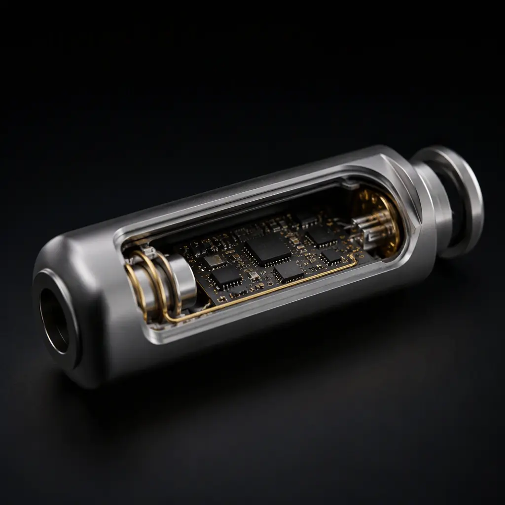
Key Takeaway: For implantables, "biocompatible PCB" mostly means the board is clean, inert and sealed. The qualification questions that matter are ionic cleanliness limits, moisture resistance and long-term corrosion testing, not marketing claims about "medical-grade" laminate.
Design Rules for a 1 cm² Board That Must Not Fail
Fitting a full system, sensing, processing, telemetry, power management, into a few square centimetres forces design choices that are rare anywhere else.
HDI microvias and stacked vias for density
Every layer transition on a 6–12 layer implantable board uses laser microvias at 0.075 mm or smaller, often stacked or staggered across multiple layers to escape ultra-fine-pitch die pads. Via-in-pad is routine. The via structures, reliability testing and IPC-4761 types are detailed in our microvia reliability guide and filled via guide.
Flex and rigid-flex for anatomical fit
Many implantables use rigid-flex construction so the electronics can wrap around the battery or conform to body geometry. The flex zones are designed with controlled bend radius and strain relief, because the device flexes with the body. Our rigid-flex PCB guide covers the design rules, and flex PCB manufacturing details the material and process limits.
Bare die and wire bonding integration
Implantable hybrid assemblies often mount bare die directly on the substrate with wire bonding, gold or aluminum wedge bonds, alongside SMT components. This is a specialised assembly capability that requires its own process qualification, cleanroom handling and bond-pull verification. The same techniques appear in the IC programming and assembly and chip-on-board assembly processes we run for high-reliability clients.
Reliability: Testing That Approximates a Decade
You cannot wait 10 years to find out if a board will survive 10 years. Implantable qualification compresses a decade of use into weeks of accelerated testing, and every test is a pass/fail gate for the product.
Thermal cycling and accelerated aging
Boards cycle between body temperature and storage extremes while the electronics run. Accelerated aging at elevated temperature models years of operation in months, and thermal cycling from −40°C to +85°C exposes marginal solder joints and microvia cracks. The methodology maps to our thermal cycling guide, with implantable pass criteria far stricter than commercial.
Vibration, shock and body-motion stress
An implant moves with every heartbeat, step and turn. Random vibration and mechanical shock testing are performed on assembled devices, not bare boards, because the interconnects and wire bonds are the vulnerable points. Our vibration and shock testing guide describes the test profiles; implantable programs add millions of flex cycles for the rigid-flex zones.
MRI safety and EMC verification
Implantable devices must survive the 1.5–3 T field of an MRI scanner without heating, migrating or malfunctioning. That requirement shapes the materials (minimising ferromagnetic content) and the layout (loop areas that couple to RF fields). The RF and EMC validation borrows from our EMI/EMC design guide but is performed on the complete implant with specialised fixtures.
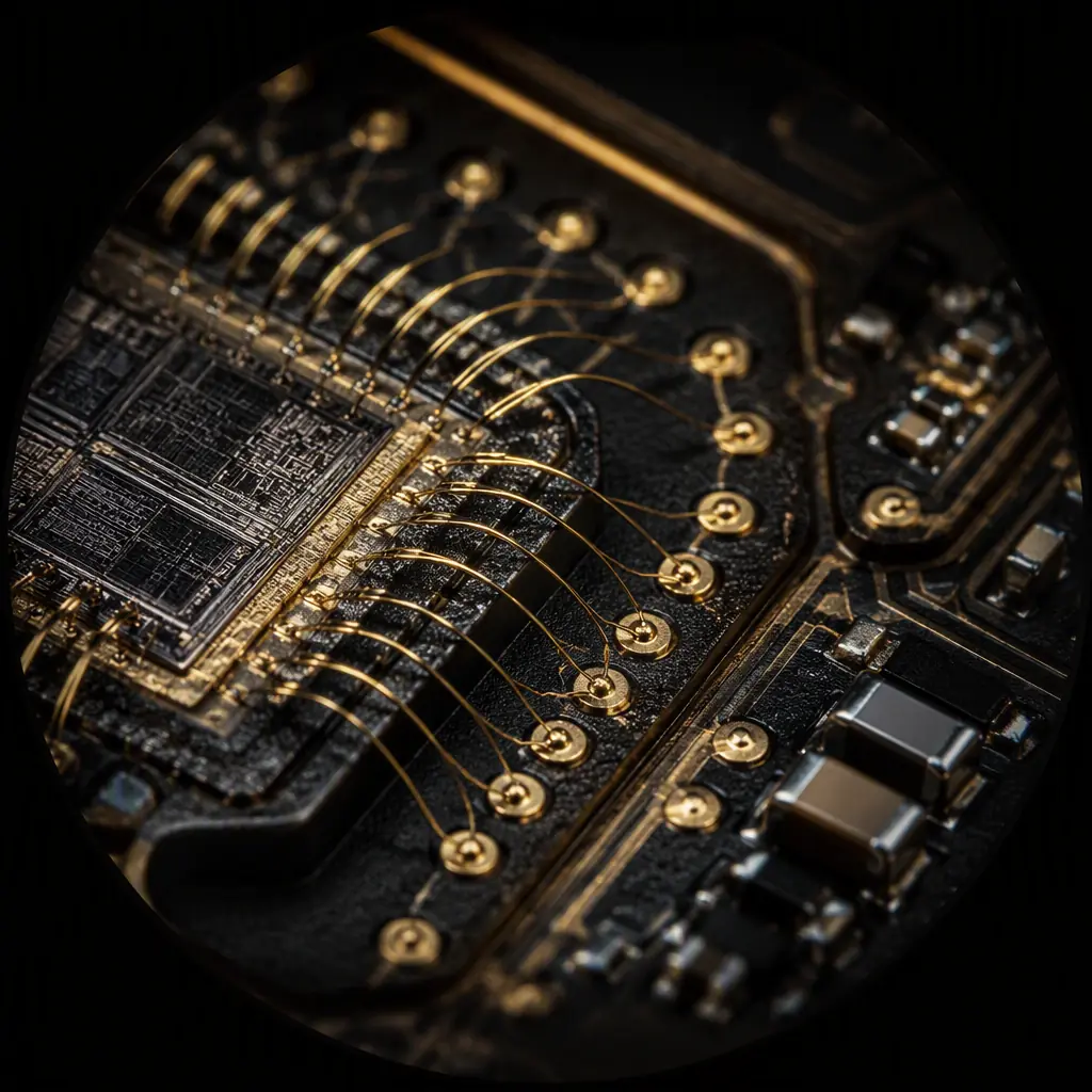
Reliability Reality: The failure modes that kill implantable boards are the slow ones, microvia cracks, ionic corrosion, intermetallic growth, wire-bond fatigue. Each is invisible at final test and fatal at year five. That is why the test plan, not the board, is the real deliverable of an implantable program.
Manufacturing Controls and Supplier Qualification
Implantable PCB manufacturing is governed by ISO 13485 and, in the US, FDA 21 CFR Part 820 requirements. The manufacturer's controls must be auditable end to end.
Full traceability per lot
Every material lot, every process step and every test result must be traceable to the individual device. Lot traceability and the IPC-1782 data standard are covered in our lot traceability guide . For implantables this is not a nice-to-have but a regulatory requirement, audited by notified bodies.
Dedicated line and process validation
The assembly line, stencil, reflow profile and cleaning process must be validated and frozen, no drifting parameters between lots. Process validation, first article inspection and the incoming inspection discipline are covered in our PCBA process guide, first article guide and incoming inspection guide. A supplier that treats implantable work as "just Class 3 with extra paperwork" is disqualifying.
Cleanroom assembly and handling
Bare die, wire bonding and hermetic sealing happen in cleanroom environments with controlled humidity and ESD protection. The ESD program requirements are in our ESD control guide, and the moisture handling rules for the fine-pitch components in our MSL guide . Both are enforced per lot for implantables.
Summary: The Implantable Board Checklist
Design for the smallest envelope the function allows, HDI microvias, 0201 and bare die, rigid-flex where the anatomy demands it. Specify materials for ionic cleanliness and corrosion resistance, not marketing claims. Qualify with accelerated aging, thermal cycling, vibration, MRI safety and millions of flex cycles. And choose a manufacturer whose traceability, process validation and cleanroom controls you can audit. Because the board's 10-year promise is really their process's promise.
At Huaxing PCBA, we build high-reliability medical boards under ISO 9001 with IPC Class 3 acceptance, including fine-pitch BGA, chip-on-board and controlled-cleanliness assembly across 8 SMT lines. Read our PCB certifications guide for the compliance landscape, or contact our engineering team to discuss the manufacturing controls your implantable program requires.
