
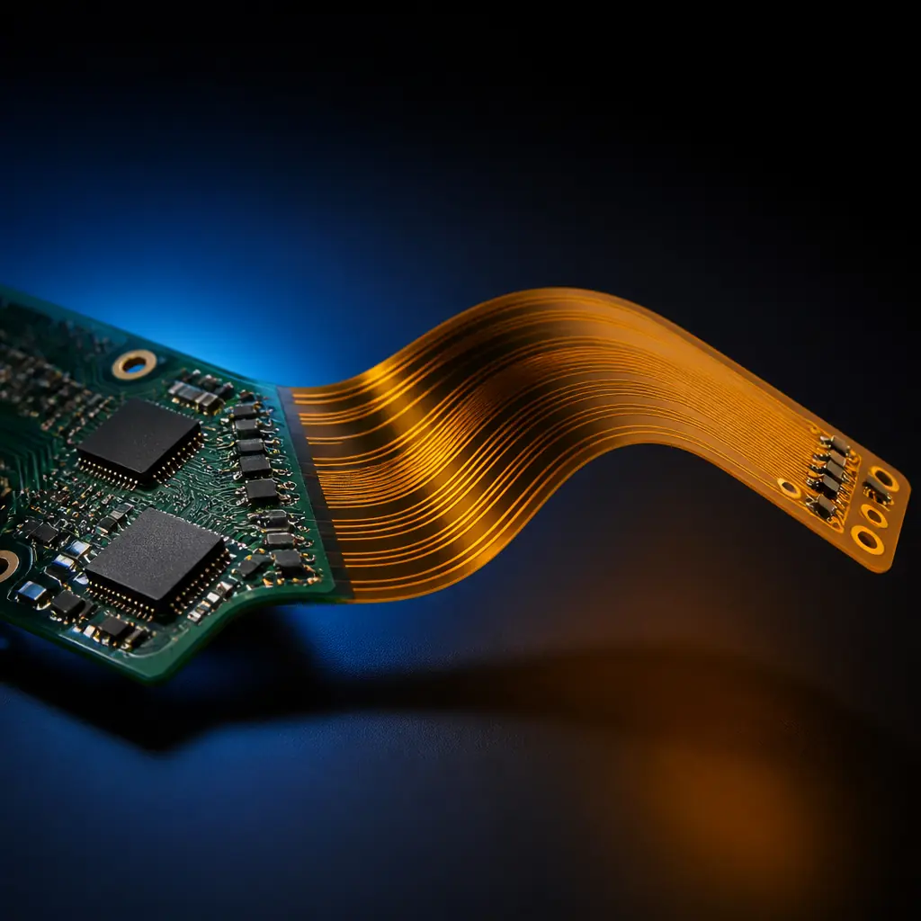
Rigid-flex is chosen for a reason that has nothing to do with cost per square inch: it removes connectors, cables and the hand-assembly labour that goes with them, and it does so while surviving the vibration and space constraints that a cable harness would fail. A rigid-flex board folds into a three-dimensional shape, supports components on rigid sections, and carries a continuous conductor through the bend. For products with a moving display, a stacked enclosure, or a sensor that has to reach into a tight volume, it can be the only architecture that fits.
The trade is that you are now buying fabrication instead of a harness, and the fabrication is more demanding. A rigid-flex build carries a flexible core through rigid sections, bonds them under heat and pressure, and then has to survive being bent during assembly and for the life of the product. Every one of those steps has design rules attached, and the rules are where the cost and the reliability are decided. A bend radius chosen for a paper sketch, a coverlay omitted where the board folds, or a stiffener left out where a connector mounts will all show up as failures on the line.
This article covers what rigid-flex is versus flex and rigid, the construction types (bookbinder, air-gap and no-bond), the bend-radius and copper rules that govern whether a fold survives, the coverlay-versus-soldermask and stiffener decisions, the cost drivers behind a rigid-flex quote, and the assembly traps such as moisture bake before reflow. For the flex-only background, see our guide to flex PCB design and manufacturing; for the stackup principles underneath, see PCB stackup design.
At Huaxing PCBA we build multilayer rigid-flex and flex assemblies across 8 SMT lines under IATF 16949 and ISO 9001, including the lamination and bend-zone controls that rigid-flex requires. The fabrication is where rigid-flex succeeds or fails, so we review the flex zones and stiffener plan before the first panel is committed.
Rigid-Flex vs Flex vs Rigid: Where the Hybrid Wins
The three architectures answer different problems, and the hybrid is not a strictly better version of either of the others.
Rigid PCB is the default: flat, mechanically stable, cheap per unit area, and full-featured for component mounting. It cannot fold, and any interconnect between two rigid assemblies has to be a connector and cable.
Flex PCB is a thin, flexible circuit — typically a polyimide base film with copper and a coverlay. It folds, survives repeated bending, and is excellent for tight or moving connections. What it lacks is the mechanical support for heavy components: mounting a connector or a large module directly on unsupported flex puts stress on the joints every time the board moves.
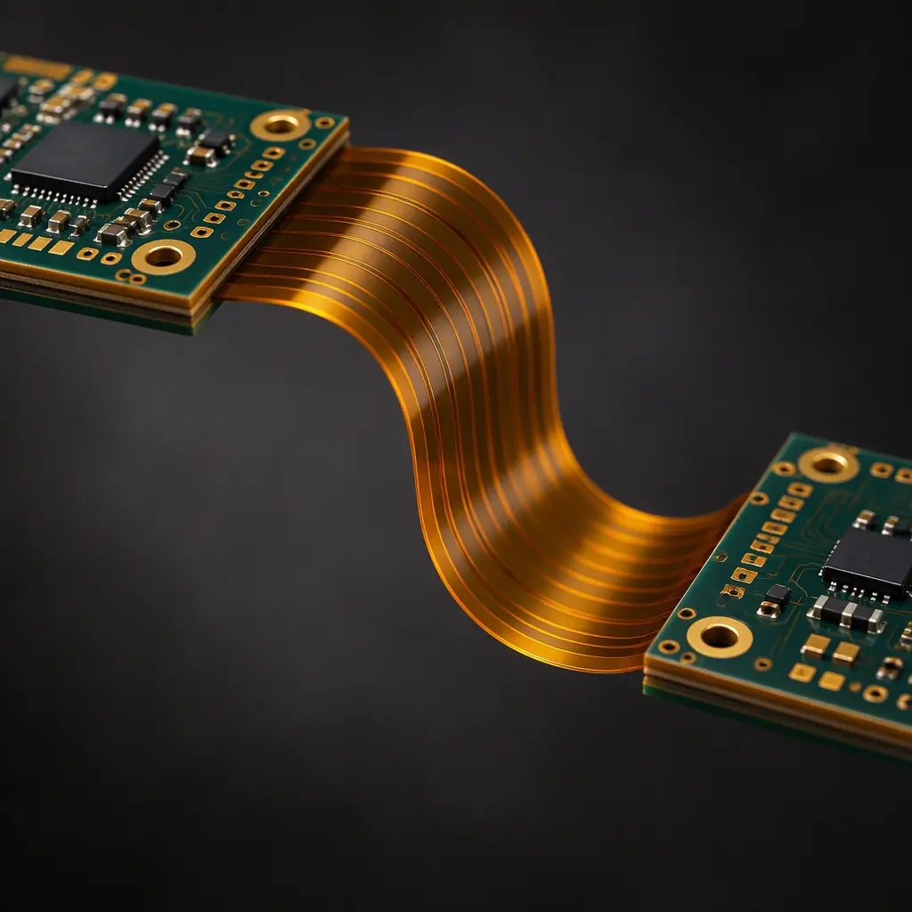
Rigid-flex combines both by laminating rigid sections to a flexible core. Components sit on rigid sections that behave like a normal PCB; the interconnections run through flexible sections that fold. The result is a single assembly that can be shaped into three dimensions, holds its connectors solidly, and deletes the cable harness entirely. The hybrid wins where you need both rigid mounting and a fold — which is why it is common in medical devices, aerospace, cameras, wearables and densely packed consumer products.
The decision point is usually mechanical, not electrical. If the assembly must fold or must reach into a constrained volume and also needs connectors or heavy parts mounted securely, rigid-flex is the architecture. If the connection is static and there is room for a connector and cable, rigid is cheaper. If everything can be thin and light and nothing needs rigid support, flex may be enough.
Construction Types: Bookbinder, Air-Gap and No-Bond
How the flexible section is built determines both the mechanical behaviour and the cost. Three constructions cover most designs.
| Construction | How it is built | Best for |
|---|---|---|
| Bookbinder | Rigid and flex layers bonded together across the full area with no separate unbonded zone; the flex is laminated into the rigid stack | Most common; good mechanical support; simpler lamination |
| Air-gap | Rigid sections are separated by an unbonded (air) region in the flex zone, creating a gap between the rigid layers | Applications needing greater flexibility or separation at the bend |
| No-bond / unsupported bend | The flexible section is deliberately left unbonded and free of stiffeners, so it can bend freely | Dynamic or tight bend zones where the flex must move |
Bookbinder construction is the workhorse. The flex core is laminated into the rigid stack with bonding across the panels, which gives the rigid sections more mechanical integrity and simplifies the lamination. Its limitation is that the bonded region reduces how freely the bend zone can move.
Air-gap construction leaves unbonded regions so the rigid sections can separate at the fold, which increases flexibility and allows tighter bends. The trade is a more demanding lamination and a design that has to keep components and plating out of the gap region.
No-bond construction is used where the flex zone must bend freely and possibly repeatedly. It requires that no part of the stack — stiffener, bonding ply, coverlay — intrudes on the bend area, because anything rigid there becomes a stress riser and a fracture point. Whatever your construction, the bend zone should contain only the conductors and the flexible dielectric.
Bend Radius and Copper Rules
The single number that most determines whether a rigid-flex design survives is the bend radius, and it is usually specified too tight. Bend radius is expressed as a ratio of the radius of the bend to the overall thickness of the flex section.
Static bends — the board is folded once during assembly and stays put — are typically allowed a tighter radius, commonly around 10:1, though a conservative design uses more. Dynamic bends — the section flexes repeatedly in use — need a larger radius, and the ratio must be generous enough to keep strain in the copper below its fatigue limit for the required cycle count. A single number cannot be assumed to cover both cases.
Copper type matters as much as radius. Rolled annealed (RA) copper is far more ductile and fatigue-resistant than electrodeposited (ED) copper, which has a columnar grain structure that cracks more readily under repeated bending. For dynamic flex zones, RA copper is the standard choice, and for tight static bends it is preferred. Using ED copper in a bend zone and expecting a long life is one of the most common rigid-flex mistakes.
Conductor routing in the bend. Traces should cross the bend perpendicular to the bend line so they experience a single, consistent strain path. Traces that run parallel to the bend, or that have plated through-holes or pads inside the bend zone, concentrate stress and become crack origins. Plated holes should be kept out of the flex zone entirely; if a connection requires a via, it belongs in a rigid section.
Coverlay, Soldermask and Stiffeners
Three material choices decide how the finished assembly behaves, and each is a place where a cost-saving instinct can hurt reliability.
Coverlay vs photo-imageable soldermask
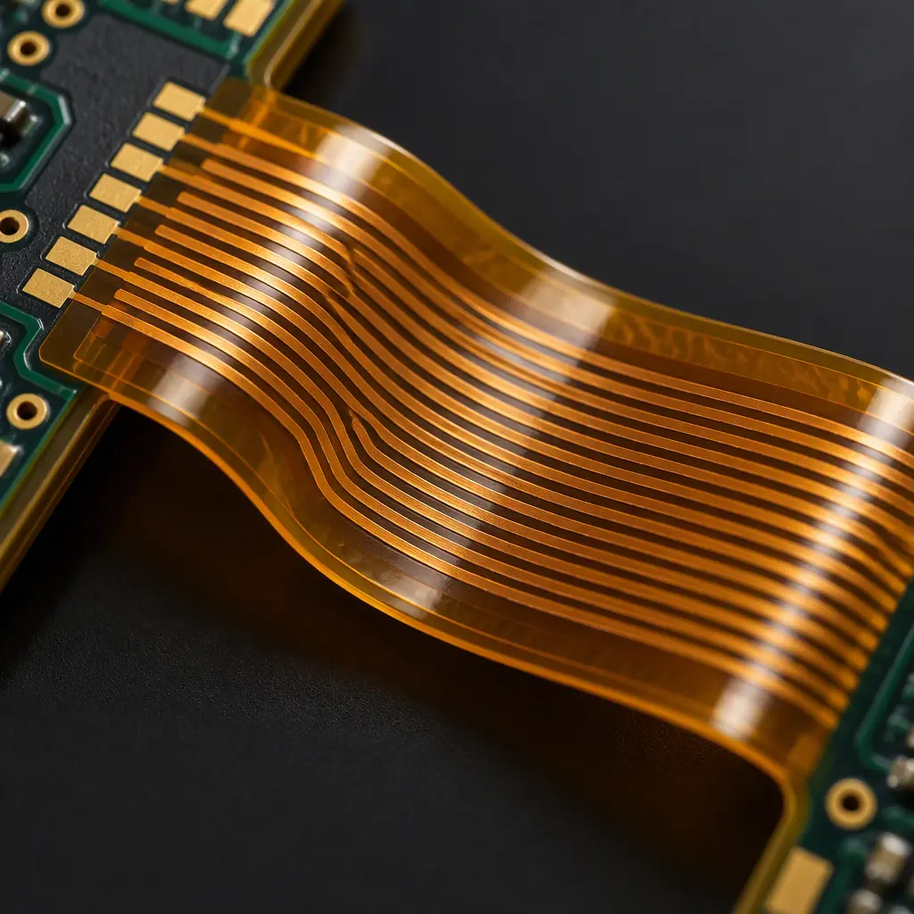
Flexible sections are usually covered with a coverlay — a polyimide film with an adhesive — rather than a standard soldermask. Coverlay is more flexible and more robust in bend zones, but its openings are less precise and it costs more. Photo-imageable soldermask is cheaper and has tighter openings, but it can be less tolerant of repeated flexing. The usual compromise is coverlay in the bend zones and soldermask on rigid sections that will not flex.
Stiffeners
A stiffener is a rigid layer — FR-4, polyimide or steel — added behind a flex region to support a connector, a component or a mounting point. Without a stiffener, connector insertion and cable pull put stress directly into the flex joints and the pad interfaces. Stiffener material and thickness should be chosen for the mechanical load, and the stiffener must stop short of any bend zone.
Bonding ply and its limits
The adhesive layers that bond the stack are part of the electrical and mechanical design. They add to the flex thickness — reducing the achievable bend radius for a given strain target — and they must not intrude into an unbonded bend zone. Bonding ply selection and thickness are often stated by the fabricator's standard stackup and should be reviewed against the bend requirement.
The pattern across all three is that cheaping out in a bend zone trades a small material cost for a large reliability risk. Coverlay, RA copper and correctly placed stiffeners are not optional refinements — they are what makes the assembly survive its service life. Our article on PCB manufacturing tolerances covers how flex-zone registration adds to the design constraint.
What Drives the Cost of a Rigid-Flex Build
A rigid-flex quote is structured differently from a rigid board quote, and understanding the drivers lets you design for cost before you go to quotation. The main ones:
Panel utilisation. Rigid-flex panels are harder to nest efficiently than rigid panels because the assemblies are often long and narrow and the flex zones cannot be populated with other parts. Poor utilisation raises unit cost even when the design is simple. Designing the rigid sections to nest well on a panel is a real cost lever.
Layer count and construction complexity. Each additional flex layer adds lamination steps, and moving from bookbinder to air-gap adds process steps. The construction type should be the least complex that satisfies the mechanical requirement.
Materials. Polyimide core, RA copper, coverlay and the bonding plies are all more expensive than their rigid-board equivalents. Specifying RA copper only where it is needed — in bend zones — rather than across the whole board can reduce cost without compromising reliability.
Stiffeners and connectors. Every stiffener adds a lamination or bonding step, and connectors add both the stiffener requirement and assembly labour. Consolidating connectors and mounting points reduces both.
Registration across flex zones. Keeping tight tolerance across a board that spans rigid and flexible regions is harder than on a flat board, and demanding tight registration in the flex zone adds cost for little benefit. Relaxing superfluous tolerance in non-critical areas lowers the price without affecting function.
Assembly Traps: Moisture, Fixtures and Connector Interfaces
Rigid-flex assemblies have failure modes that a rigid board does not, and most of them appear during assembly rather than at fabrication.
Moisture bake before reflow. Polyimide and the adhesive systems absorb moisture, and a rigid-flex assembly that goes into reflow without a bake can suffer delamination or blistering in the flex zones as the trapped moisture expands. Because the flex sections are thin and the laminates are moisture-sensitive, the dry-pack and bake schedule is more critical than for a rigid board, and it must be followed even when the assembly appears dry. If you receive rigid-flex in sealed packaging, the storage and moisture-control schedule applies the same way it would to a rigid board with moisture-sensitive devices.
Fixtures and handling. The bend zone should not be clamped or gripped during assembly; a fixture that supports the assembly by its flex section puts stress exactly where it is least tolerable. The fixture should support the rigid sections and leave the bend zone free.
Connector interfaces. Connectors mounted on flex without an adequate stiffener can suffer pad lift or open joints under insertion force. The stiffener requirement should be driven by the connector's insertion and retention loads, not by what looks structurally sufficient to the eye. Our guide to high-speed connector PCB design covers the routing and mechanical side of connector interfaces.
Summary: A Fabrication Problem Wearing an Electrical Costume
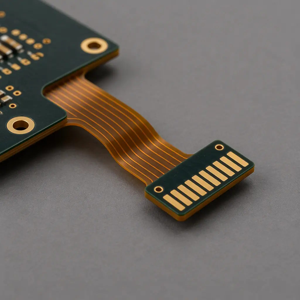
Rigid-flex is chosen for mechanical reasons — it folds, it reaches, it survives vibration — and the design that makes it work is mechanical: construction type, bend radius, copper type, coverlay placement and stiffeners. Get those right and the assembly deletes a harness and its labour; get them wrong and the cost shows up as line failures. Cost is driven by panel utilisation, layer count, materials, stiffeners and tolerance requirements, all of which can be designed down before quotation. The bend zone should contain only conductors and flexible dielectric, dynamic bends need generous radii and RA copper, and any interface that takes mechanical load needs a stiffener behind it.
At Huaxing PCBA we build multilayer rigid-flex and flex assemblies with lamination, bend-zone and stiffener controls across 8 SMT lines under IATF 16949 and ISO 9001. If you are weighing rigid-flex against a connector-and-cable architecture, send us the design early and we will review the flex zones and stackup before you commit. Send your Gerber and BOM and we will return a quote with the DFM review inside 24 hours, or talk to our engineering team about a rigid-flex stackup or bend-zone question you are working through.
