
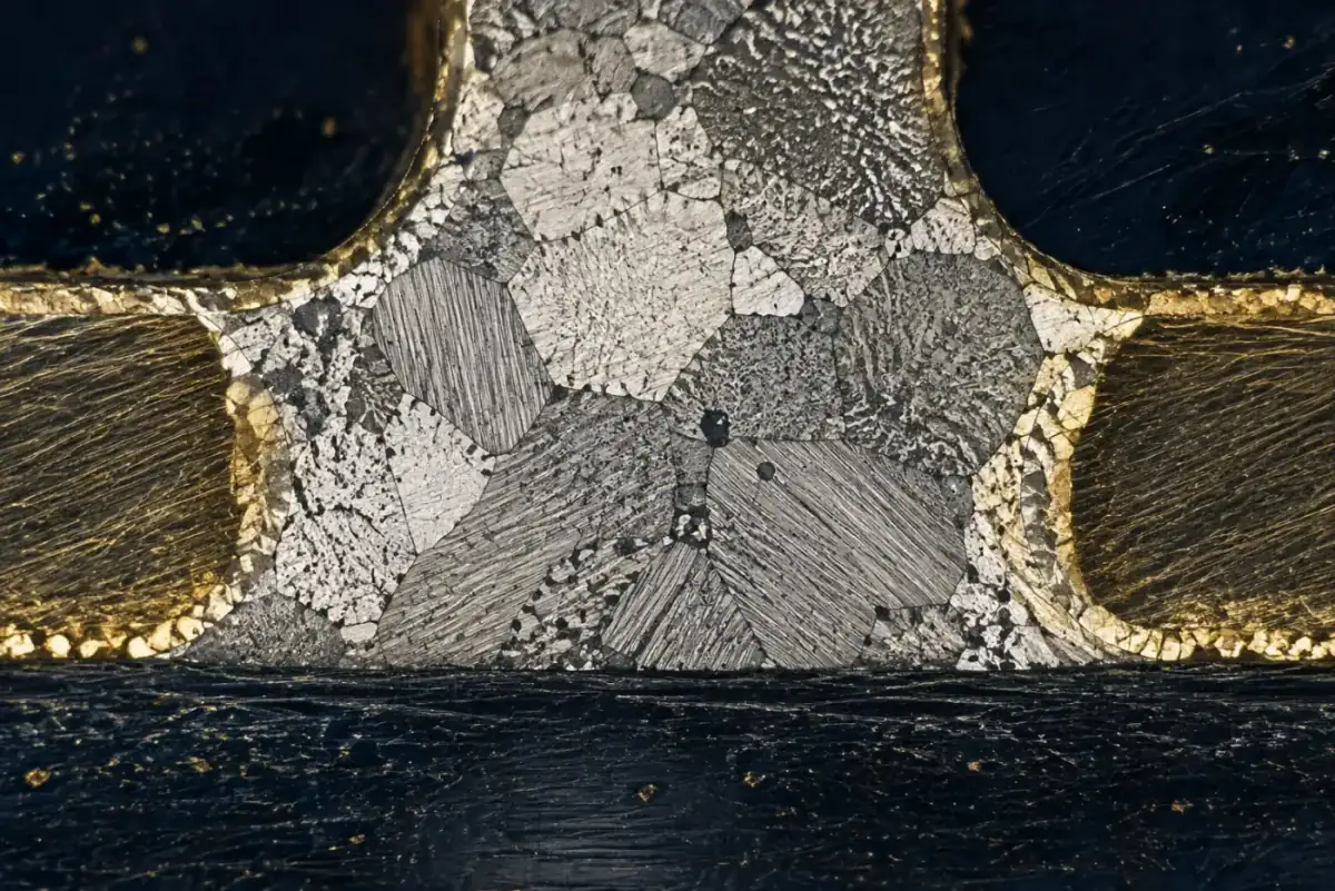
Mixed-alloy assembly — a lead-free board carrying leaded components, or a leaded board carrying lead-free parts — is one of the most common and least understood situations in contract electronics manufacturing. It arises on legacy product transfers, on repairs where original alloy parts are unavailable, on boards that combine modern fine-pitch area-array devices with an odd legacy connector, and on programmes where a customer's reliability standard conflicts with the RoHS directive. In each case the process is legal and workable, but the reliability implications are specific and measurable and they must be decided deliberately rather than discovered at the reflow oven.
The central technical problem is simple to state. When tin-lead and tin-silver-copper alloys mix in a joint, the resulting composition does not sit between the two melting ranges — it forms a low-melting phase, in some ratios as low as approximately 175–179°C, lower than either parent alloy. That phase concentrates at the joint interface and becomes the mechanically weakest point in the assembly, and it will not anneal away. At Huaxing PCBA, mixed-alloy programmes are handled with an explicit written process decision and thermal cycling validation rather than a default profile, and the reason is precisely this phase behaviour.
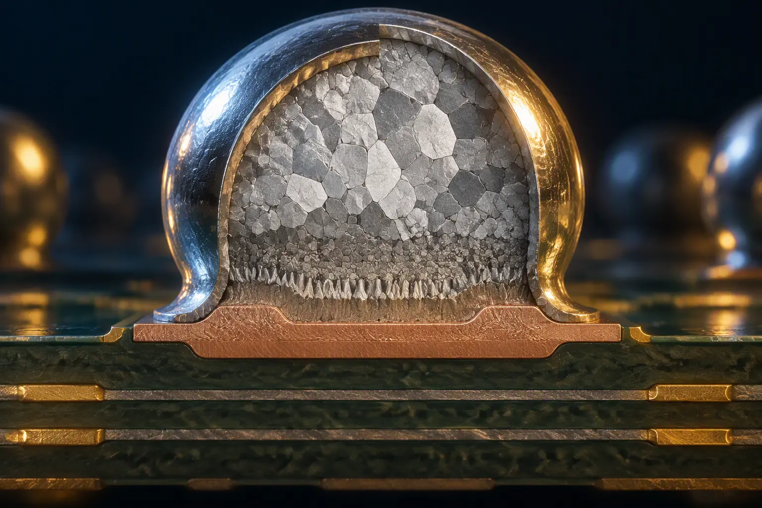
Why Mixed Alloy Joints Behave Differently
Four physical effects drive the reliability risk, and each one maps to a different rejection mode in the field.
Low-Melting Phase Formation
Mixing SnPb (eutectic at 183°C) with SAC305 (solidus approximately 217°C, liquidus approximately 220°C) does not produce an alloy with an intermediate melting point. Depending on the ratio, it produces a ternary or quaternary composition with a solidus as low as roughly 175°C — below both parent alloys. This phase typically forms fillets, bands and interface layers within the joint, and its lower melting point means that under subsequent thermal exposure — including a second reflow pass, a rework operation, or elevated service temperature — it can partially remelt while the rest of the joint stays solid. The practical consequence is that a mixed-alloy joint can fail at a temperature at which the individual alloys would be entirely stable.
Reduced Thermal Fatigue Life
The low-melting phase is softer and coarser than either parent alloy and concentrates stress under thermal cycling. Crack initiation tends to occur within this phase or at its boundary, and propagation is accelerated. Published thermal cycling studies on mixed-alloy joints consistently show reduced cycles to failure relative to either all-SAC305 or all-SnPb joints, with the magnitude depending on the phase volume fraction and the temperature excursion profile. For a product that will see automotive-grade thermal cycling — typically −40°C to +125°C, 1,000 cycles or more — this is the difference between passing qualification and rewriting the qualification plan.
Incomplete Melting and Head-in-Pillow Risk
If the reflow profile is set for leaded parts, the SAC305 ball on a BGA may not fully reflow even though the surrounding paste does. This produces a partially melted joint where the ball and the paste have not fully coalesced — a head-in-pillow defect. It passes X-ray in many cases and fails either at functional test or in the field. Our guide to BGA assembly and X-ray inspection covers why BGA joints are the most sensitive to this failure mode and how inspection can miss it.
Component Temperature Limits
The higher peak temperature required to ensure complete SAC305 melting (typically 235–245°C peak) is above the rated maximum for some legacy and moisture-sensitive components. Mixed assembly therefore often faces an unavoidable conflict: temperature high enough to reflow the lead-free alloy can damage the very leaded parts the mixed process exists to accommodate. Resolving that conflict is the main technical work in any mixed programme. Our lead-free versus leaded alloy comparison covers the underlying thermal behaviour of both families.
Key Takeaway: A mixed-alloy joint is not simply "somewhere between" leaded and lead-free. The low-melting phase it contains can be the lowest-melting material anywhere on the assembly, which makes it the first thing to fail under thermal cycling and the hardest to detect. Decide the alloy strategy before the design is frozen, not at the reflow oven.
Which Combination You Actually Have
"Mixed assembly" covers several distinct scenarios with materially different risk profiles. Identify yours precisely, because the process rules differ.
| Scenario | Joint Composition | Risk Level | Practical Approach |
|---|---|---|---|
| SAC paste with SnPb-plated component leads | Predominantly SAC with thin SnPb plating dissolving into the joint | Low to moderate | Standard SAC profile; quantify Pb contamination by alloy analysis; acceptable for Class 2 with records |
| SAC paste with SnPb solder balls (legacy BGA) | Significant intermixing, phase formation at collapse | High | Requires profile development to ensure full melting and thermal cycling validation; avoid for Class 3 |
| SnPb paste with SAC component balls | Substantial unmelted SAC ball with low-melting interface | Very high | Generally not recommended; the SAC ball will not fully reflow at SnPb temperatures, producing head-in-pillow |
| SAC paste with SnPb through-hole connectors (selective solder) | Localised mixing at the barrel | Moderate | Selective soldering with controlled local heating; keep mixed joints away from high-stress locations |
| Hand-soldered repairs on a lead-free board with SnPb wire | Mixed at the repair joint only | Moderate | Acceptable for repair under IPC-7711/7721 with documentation; not acceptable as production intent |
The last row deserves emphasis because repair is where mixed alloys appear most often without anyone planning for them. A board originally assembled lead-free that is repaired with leaded wire and flux is no longer a lead-free assembly, and RoHS documentation claiming otherwise is incorrect. If the product has a lead-free declaration, repairs must be performed with compatible lead-free alloy, or the declaration must be revisited. Our rework and re-coating guide covers the documentation standard that applies to reworked boards.
Profile Development for Mixed Assemblies
If mixed assembly is unavoidable, the reflow profile becomes the primary control. The objective is to bring the entire joint, including any higher-melting component alloy, above its liquidus for long enough to form a single homogeneous joint, without exceeding the thermal limits of the most sensitive component on the board.
Establish the Thermal Envelope First
List the maximum rated temperature and maximum exposure time for every component on the board, including moisture sensitivity level and body temperature limits. The most restrictive item sets your ceiling. Common constraints are electrolytic capacitors (often 250°C for 10 seconds at body), plastic-bodied connectors, and legacy through-hole parts rated for leaded-only profiles. Document this envelope before you design the profile; it usually determines whether mixed assembly is viable at all.
Profile for the Highest-Melting Alloy, Not the Paste
The common error is to profile for the paste and assume the component alloys follow. If a legacy BGA with SnPb balls is present, profiling to a SAC paste curve is correct for the paste but may overheat adjacent leaded parts. If a SAC-balled BGA is being soldered with SnPb paste, the profile must exceed the SAC liquidus to melt the ball, which will exceed the SnPb paste's rated limits. In practice only the first of these is routinely solvable, and it requires careful thermal mapping.
Measure, Do Not Assume, the Peak at Every Critical Location
Attach thermocouples to the actual problematic components — the BGA corner and centre, the legacy connector pins, the heaviest thermal mass on the board — not to a test coupon. In mixed assemblies the spread between the hottest and coldest location on the board is often larger than in homogeneous assemblies because thermal masses differ more. Our reflow profile optimisation guide covers the three-pass validation methodology that should be applied here.
Validate With Cross-Section and Thermal Cycling
A mixed-alloy process is not validated by a passing AOI result. Two additional evidence streams are required. First, cross-section a sample of the mixed joints and examine them metallographically for low-melting phase distribution, voids and interfacial structure — this shows you what the joints actually contain. Second, run thermal cycling to the service profile the product will see and compare cycles-to-failure against an all-one-alloy control. Without both, there is no basis for claiming the mixed process is equivalent. Our via reliability test comparison explains how thermal cycling and IST differ as qualification evidence.
Document Alloy Contamination in the Data Package
For any mixed assembly, the data package should state the alloys present, the measured lead content in the solder joints where relevant, the profile used, and the validation evidence. This matters for RoHS declarations, for customs documentation, and for any subsequent failure analysis. Record the actual measurement rather than an assumed nominal value. Our RoHS compliance guide covers the exemption analysis that determines whether a mixed assembly can lawfully carry a lead-free declaration.

Standard and Class Constraints
IPC-A-610 permits mixed-alloy assembly for Class 1 and Class 2 products provided the process is documented. For Class 3 — the class that applies to aerospace, defence, medical life-support and other high-reliability work — the standard recommends against mixed assembly unless it is validated with supporting thermal cycling data, and many Class 3 programme offices treat mixed joints as a non-conformance outright.
The practical rule that follows: treat mixed assembly as acceptable by exception, not by default. Where the product is genuinely Class 3, or where the thermal environment is severe, or where the joint will carry significant mechanical load, the correct engineering answer is normally to eliminate the mixing rather than to characterise it. Options include sourcing the component in a lead-free termination finish, changing the paste to match the component ball alloy, or moving the legacy part to a hand-soldered or selective-soldered operation that is physically separated from the mixed joint. Our J-STD-001 assembly standard guide covers how the class-dependent requirements propagate through the process specification.
Procurement tip: If a supplier proposes mixed-alloy assembly on your programme, ask three questions in writing: which specific joints will be mixed; what peak temperature and time-above-liquidus was actually measured at those joints; and what thermal cycling data supports the reliability claim. A supplier with a controlled process will answer with numbers and a cross-section report. A supplier without one will answer with reassurance. The full set of process records to request is listed in our test report and documentation guide.
Summary / Next Steps
Mixed-alloy assembly is technically viable and commercially common, but it carries a specific reliability penalty caused by low-melting phase formation at the joint interface. Manage it by identifying the exact scenario, profiling to the highest-melting alloy within the component thermal envelope, verifying with cross-sections and thermal cycling rather than AOI, and documenting the alloys and measurements in the data package. Where the product is Class 3 or thermally severe, prefer eliminating the mix over characterising it.
At Huaxing PCBA, mixed-alloy programmes are quoted with an explicit written process decision, a thermal envelope review across every component on the BOM, cross-section reporting on the joints that matter, and thermal cycling validation where the class or application requires it — all under an IATF 16949 and ISO 9001 quality system with full traceability. Our engineering team runs solderability testing and cross-section analysis as standard evidence for alloy decisions, or contact us to review your mixed-alloy programme before the design is frozen.
