
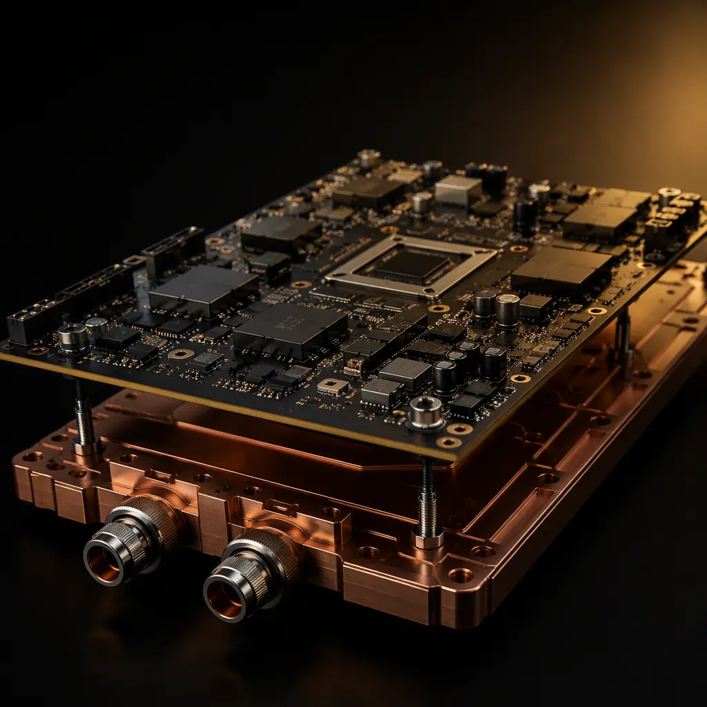
A modern AI accelerator or server CPU routinely draws 700 W and north of that as density ramps. A high-power converter stage in an EV traction inverter or a data-center power module is not far behind. At that level, the heat flux at the package can exceed 1 W/mm², and the board beneath it is no longer just a place to mount components. It is the first link in the path that carries that heat away.
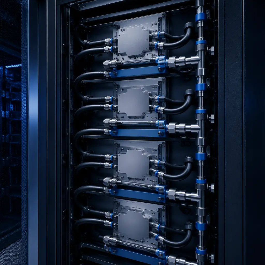
Air cooling simply cannot keep up at these densities, which is why the industry has moved to cold-plate direct liquid cooling (DLC), where warm outlets and cold plates carry a coolant that extracts heat at the source. The consequence for the PCB is a set of requirements that a conventional FR-4 commercial board was never designed to meet: thick copper for current, copper inlay or coin for spreading, a dense thermal-via field, and a flat, contamination-tolerant surface that the cold plate seals against. At Huaxing PCBA we fabricate boards with heavy copper up to 6 oz, 32-layer any-layer HDI and controlled impedance to ±5% . The toolkit a liquid-cooled power board needs.
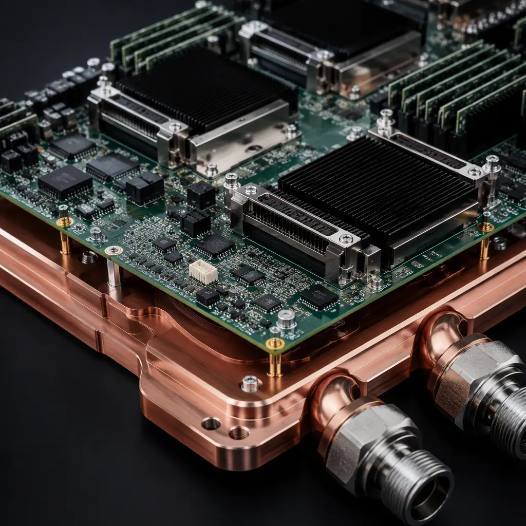
Cold Plate vs Immersion: Two Ways To Get The Heat Out
The two liquid approaches solve the same problem differently, and they place very different demands on the board.
| Approach | How it works | Board demand |
|---|---|---|
| Cold plate (DLC) | Coolant circulates through a cold plate bolted to the package | Copper inlay / coin, thermal vias, flatness, clean surface |
| Immersion | Whole board submerged in dielectric fluid | Material compatibility, no corrosion, no coating gaps |
Cold-plate cooling is where most of the AI and high-density server volume is going, because it adds the least risk and keeps the servicing model familiar. Immersion has its own niche. For how the two interact with materials and coatings, see our immersion-cooled PCB design guide and the general thermal management guide.
Copper Inlay And Coin: Spreading The Heat Before It Becomes A Blowtorch
The single biggest lever on a liquid-cooled board is what sits directly under the hot die. A standard PCB laminate is a poor conductor of heat, roughly 0.2–0.3 W/m·K through the thickness, against copper at around 390 W/m·K. The gap is what drives the use of copper inlay and copper coin.
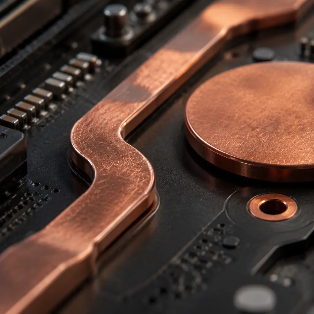
Copper coin / inlay under the hotspot
A solid copper slug pressed or plated into the board directly under the package spreads heat laterally into the cold plate. This is the difference between a board that survives a load spike and one that delaminates. The heat-spreading fundamentals are worth a read.
Heavy copper for the power path
Power delivery to a 700 W processor needs substantial copper for both current capacity and low resistance. We build with 0.5 oz to 6 oz copper and choose the weight from the current, not from habit. Our copper weight selection and trace current capacity guides give the numbers.
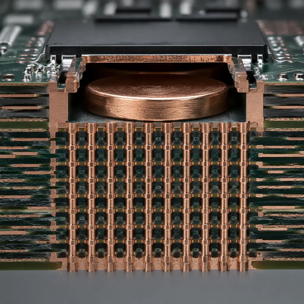
Thermal vias under the power pad
A filled via array under the exposed pad shunts heat down to the cold-plate side. Via pitch and fill do the work, at 0.3–0.4 mm pitch in a dense field. The via technology and via fill guides cover the options.
The Thermal-Via Budget Is A Number, Not A Good Idea
Thermal vias are not decorative; they have a calculable contribution. A single filled via can carry a specific amount of heat over a given temperature rise, so a 700 W processor with a target junction-to-case resistance needs a specific number of them. Underestimate the field and the junction temperature climbs at full load; oversize it and you take up routing space for no benefit.
More important than count is quality. Vias that are partially filled or poorly plated create voids that trap heat and invite failures under thermal cycling. Which is exactly what a liquid-cooled board experiences every time the fan or pump changes speed. Filled and capped vias keep the heat path solid and the solder joint reliable. The reflow profile and underfill interplay also matters for the BGA side.
Copper inlay and coin add cost, so they are justified where the concentration of heat demands them: typically under the processor, the memory controller and the VRM power stage. Elsewhere on the board, a simpler approach may be enough. This is the sort of trade-off a DFM review should catch before fabrication. See our DFM tips and the high-power design angle for guidance.
Surface And Sealing: Where The Cold Plate Meets The Board
A cold plate works only if it makes intimate contact. On the board side, that means a flat, clean surface and a thermal interface material that fills the remaining micro-gap. Two things go wrong here routinely:
Flatness and warpage
An uneven board leaves an air gap that behaves like a thermal resistor. Build the board flat and keep the board thickness and copper balance even so reflow and the cold-plate stack do not bow it. Board thickness selection is covered in our thickness guide.
Contamination and corrosion
Any residue under the cold plate becomes a reliability issue, and the wetted surfaces need to tolerate the coolant chemistry. Keep ionic contamination low, see our cleanliness guide, and account for the coolant in the finish choice.
Key Takeaway: A liquid-cooled power board is engineered as a heat path, not as a mounting surface. Put copper inlay or coin under the hotspot, size the copper weight from the current not habit, budget a real number of filled thermal vias beneath the power pad, and insist on a flat, clean surface where the cold plate seals. Because at 700 W the board either conducts the heat or it does not.
Summary, Build The Heat Path First
As processors and power stages push past a few hundred watts, the board is the first and most under-specified element of the cooling loop. Set the thermal budget up front, choose the copper build and via field from it, and call out flatness and cleanliness on the drawing so the cooling loop can actually close.
At Huaxing PCBA we fabricate high-power and server boards with heavy copper to 6 oz, 32-layer any-layer HDI, filled thermal vias and copper coin, to IPC-A-610 Class 3 acceptance. We are ISO 9001 and IATF 16949 certified and deliver to customers in 30+ countries on a 99.2% on-time basis. Send your stackup for a free thermal DFM review or talk to a project manager about your liquid-cooled design.
