
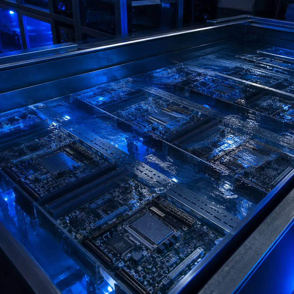
Immersion cooling moves from pilot projects to mainstream deployment faster than any cooling technology in data center history. A single rack in a two-phase system now dissipates 100 kW or more, where the same footprint in air handles roughly 30 kW. But the boards inside that tank face an environment no standard server PCB was designed for: permanent contact with engineered dielectric fluids, thermal cycling through boiling points, and chemical exposure measured in years, not months.
At Huaxing PCBA, we manufacture boards for AI accelerator servers, 800G optical modules, and high-layer-count switch fabrics, the exact products now being qualified for immersion cooling. This guide covers the five decisions that determine whether an immersion-cooled board survives its service life: fluid compatibility, laminate selection, conformal coating, surface finish, and the layout rules that keep fluid flowing where it should. For the broader thermal picture, start with our PCB thermal management guide.
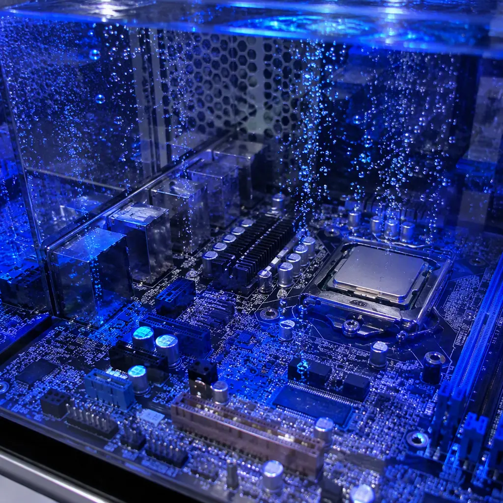
Single-Phase vs Two-Phase: Why the Fluid Choice Changes Your PCB Specs
Before touching the PCB, you must know which fluid family your system uses. The two architectures impose completely different chemical and thermal stresses on the board.
Single-phase systems, synthetic esters and polyalphaolefins
Fluid stays liquid; heat transfers by convection. Fluids such as synthetic ester-based coolants and PAO blends have excellent material compatibility with most electronics plastics, but they are aggressive solvents toward some adhesives, tapes, and low-grade elastomers. Boards run at 60-70°C fluid temperature, which is gentle thermally but means the board is soaked in liquid for its entire life.
Two-phase systems, fluorinated fluids with a boiling point around 49-61°C
The fluid boils on hot components and condenses on a cold plate, giving 10-100× better heat transfer per unit area. The board sees repeated immersion in boiling fluid, a vapor-liquid cycling environment that stresses coatings and seals far harder than single-phase. With major fluorinated fluid producers exiting the market by end-2025, many 2026 designs are re-qualifying alternative fluids or migrating to single-phase, which means the PCB qualification matrix must be re-run.
Dielectric strength is the safety spec nobody skips
Engineered immersion fluids are specified at 35-45 kV dielectric strength per 2.5 mm gap, far above air. That is what makes bare high-voltage traces safe in a tank. But dielectric strength drops as the fluid absorbs moisture or degrades, so the PCB's own creepage and clearance design still matters. Our high-voltage PCB design guide covers the spacing rules that apply here.
Key Takeaway: Two-phase is harsher on the board than single-phase. If your system may switch fluid families during qualification, design the PCB for the harsher case, two-phase compatible coatings and finishes work in single-phase, but not always the reverse.
Laminate Selection: Moisture Absorption Is the Hidden Killer
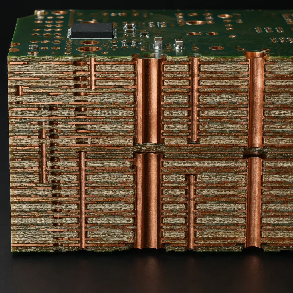
In air, a standard FR-4 board's moisture absorption of 0.1-0.25% rarely matters. Submerged in fluid, the laminate becomes the primary barrier between copper traces and the environment. Fluid wicks into board edges and along glass weave, and if the resin system absorbs moisture, the board's electrical properties drift over time.
Specify high-Tg, low-moisture-absorption laminates
Standard FR-4 (Tg 130-140°C) absorbs 0.20-0.25% moisture. High-Tg FR-4 (Tg 170°C) and modified epoxy systems drop that to 0.10-0.15%. For two-phase systems, where boards cycle near the fluid boiling point for years, low-loss/high-Tg materials used in data center server PCBs . Such as mid-loss and low-loss grades. Are the sensible baseline rather than the premium option.
Watch CTE and Z-axis expansion in cycling environments
Two-phase immersion means the board repeatedly heats and cools through a 40-60°C swing. Laminates with matched CTE reduce stress on plated through-holes and microvias. If your design uses HDI with stacked vias, review the material's Td (decomposition temperature), you want 340°C or higher for long-term stability. Stackup planning guidance is in our PCB stackup design guide.
Edge sealing: the cheapest reliability upgrade available
Fluid ingress almost always starts at the board edge, where the glass weave is exposed after routing. Specify edge sealing (edge plating or a sealed edge coating) on immersion boards, it blocks the wicking path that drives 80% of field failures in early immersion deployments. Combined with the right coating, edge sealing turns a 3-year board into a 10-year board.
Conformal Coating: Parylene vs Acrylic vs Silicone for Fluid Environments
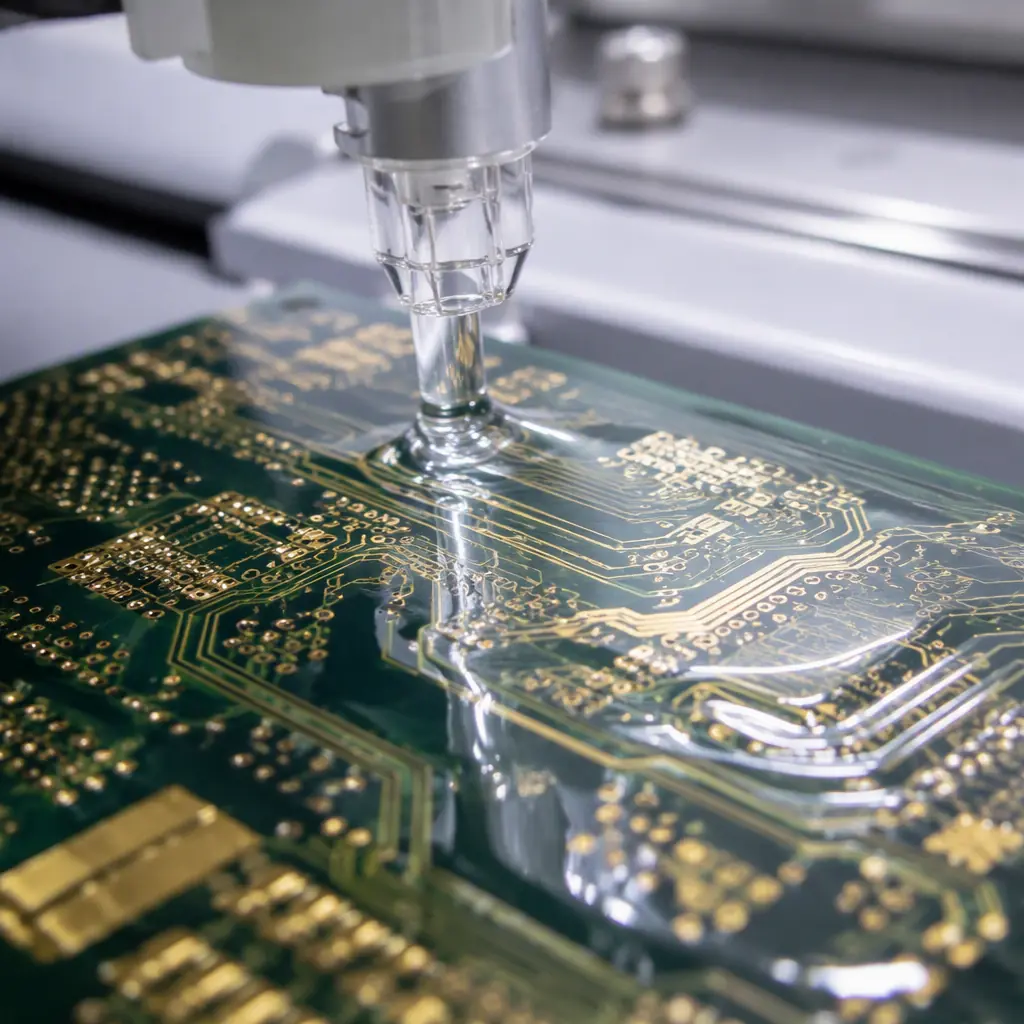
Conformal coating is the single most specified element of an immersion-cooled PCB. The right coating protects components and traces from fluid contact; the wrong one delaminates, softens, or traps fluid. Material selection fundamentals are covered in our conformal coating guide . Here is how the choice changes for immersion.
| Coating | Thickness | Fluid Resistance | Coverage Quality | Best For |
|---|---|---|---|---|
| Parylene C | 1-25 µm | Excellent | Conformal, pinhole-free | Two-phase, long service life |
| Silicone (SR) | 25-250 µm | Excellent | Thick, absorbs stress | Single-phase, high-thermal-cycling boards |
| Acrylic (AR) | 25-75 µm | Good | Easy rework | Prototypes, quick qualification |
| Polyurethane (UR) | 25-75 µm | Good-Fair | Hard, abrasion resistant | Single-phase, mechanical protection |
Parylene C is the two-phase default, with a thickness caveat
Vapor-deposited Parylene C conforms to every surface including under BGAs, with no liquid pooling or meniscus effects. At 10-25 µm it is effectively pinhole-free and resists fluorinated fluids well. The trade-off: it is expensive (roughly 3-5× acrylic), requires masking of connectors, and is nearly impossible to rework. For production boards destined for two-phase tanks, that cost is justified.
Silicone for single-phase and high-cycling boards
Silicone coatings remain flexible through wide temperature swings, ideal for single-phase systems where boards sit at 60-70°C indefinitely. They resist synthetic ester fluids well. The weakness is thickness (50-250 µm typical), which can interfere with connectors and press-fit zones, and softer surfaces that collect dust before sealing.
Masking strategy decides your rework cost
Every connector, test pad, and mating surface must be masked before coating. Plan the keep-out zones in the layout phase. A board designed for coating has test points clustered and connectors grouped on one edge, which cuts masking cost by 30-40% versus a board that treats coating as an afterthought. If full coating is overkill for part of the board, our potting vs coating guide explains selective encapsulation alternatives.
Surface Finish and Component Selection Under Fluid
Not every PCB surface finish tolerates years of fluid contact, and some components, especially electrolytic capacitors and low-grade plastics, react poorly to immersion.
ENIG and ENEPIG beat immersion finishes for corrosion resistance
Immersion silver (IAg) can tarnish in sulfur-bearing environments and dissolves slowly in some ester fluids; immersion tin is thin and reactive. ENIG (2-5 µm Ni / 0.05-0.1 µm Au) and ENEPIG give the corrosion margin immersion boards need, especially for long service life. The full comparison is in our surface finish selection guide.
Component-level compatibility is a bill-of-materials issue
Aluminum electrolytic capacitors are the most fluid-sensitive components on a server board, their rubber seals and aluminum cases degrade in esters. Specify polymer or film capacitors in fluid-contacted areas, or require the CM to verify each capacitor's fluid compatibility data sheet. Plastic housings, O-rings, and adhesives should be checked against the fluid vendor's compatibility chart before design freeze.
Soldermask: standard LPI works, but verify adhesion
Standard liquid photoimageable soldermask performs well in immersion fluids when properly cured. The failure mode is under-cured mask lifting in two-phase boiling zones. Specify the mask cure schedule per the supplier's recommendation and add a tape-pull adhesion check after fluid soak testing. Solder mask options and their limits are detailed in our solder mask types guide.
Layout Rules That Keep Fluid Flowing and Signal Integrity Intact
Immersion changes the mechanical environment of the board: fluid must flow around and through it, and the board must not trap gas bubbles in two-phase systems. The electrical environment changes too, the dielectric constant of the surrounding medium rises from 1.0 (air) to 2.0-2.4 (fluid), which alters impedance of exposed traces.
Leave flow channels, not dead zones
Orient tall components (heatsinks, connectors, capacitors) so fluid flows across their long axis. Avoid dense component walls that create stagnant pockets, in single-phase systems, stagnant zones run 10-15°C hotter than the fluid; in two-phase systems they trap vapor and stall boiling. Keep 5-10 mm of open channel on at least two opposite board edges.
Account for the fluid's dielectric constant in impedance calcs
A microstrip trace that is 50 Ω in air drops to roughly 40-42 Ω immersed in a 2.2-Dk fluid because the effective dielectric constant rises. Controlled-impedance nets that cross exposed board areas need re-simulation with the fluid as the top dielectric. This matters most for PCIe Gen5/Gen6 and 800G optical lanes. Signal integrity rules for these speeds are in our signal integrity guide.
Thermal vias and copper weight still do the heavy lifting
Immersion cooling removes the need for huge finned heatsinks, but the board-to-fluid interface still relies on thermal vias under hot components and adequate copper weight in power planes. A 2 oz inner-layer plane with a dense via array under the CPU socket conducts heat into the fluid far more efficiently than a thin 1 oz plane. High-current and thermal design rules are covered in our heavy copper PCB guide and trace width guide.
Procurement Tip: When requesting quotes for immersion boards, attach a fluid compatibility requirement sheet. A CM that asks for the fluid datasheet, coating thickness target, and soak-test duration is one that has done immersion work before, that experience shows up in your field failure rate.
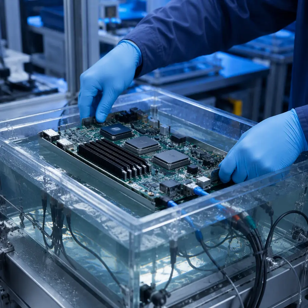
Qualification Testing: Proving the Board Survives a Decade Submerged
An immersion-cooled board cannot be qualified with the standard air-cooled test matrix alone. Add these tests before production ramp:
Fluid soak at elevated temperature, 1000 hours minimum
Soak populated boards in the actual system fluid at the maximum operating fluid temperature for at least 1000 hours, then verify coating adhesion, soldermask adhesion, impedance drift, and insulation resistance. Boards that pass 1000 h at temperature typically pass 5+ year field exposure.
Immersion thermal cycling for two-phase designs
Cycle boards through the fluid's boiling-condensing range (e.g., 30°C to 70°C) for 500-1000 cycles, monitoring for coating delamination and via barrel cracks. This complements standard thermal cycling per IPC-9701 and catches failures that air-cycling misses because the fluid changes the thermal transfer profile.
Dielectric and leakage checks while submerged
Measure insulation resistance and hi-pot performance with the board immersed and powered. A properly coated board holds >100 MΩ between adjacent high-voltage nets; any reading below 10 MΩ indicates a coating defect or fluid incompatibility that must be resolved before production.
Cost Reality: What Immersion Adds to the Board
Immersion does not multiply PCB cost, it adds specific, predictable line items. Plan for a board-level premium of roughly 15-35% over an equivalent air-cooled board:
| Cost Driver | Typical Add-On | Notes |
|---|---|---|
| High-Tg / low-loss laminate | +5-15% | Depends on layer count and material grade |
| Parylene C coating | +5-12% | Thickness and masking complexity drive price |
| ENIG / ENEPIG finish | +2-5% | vs HASL baseline |
| Edge sealing | +1-3% | Routed-edge seal or edge plating |
| Fluid qualification testing | One-time NRE | Soak, cycling, dielectric, budget 2-4 weeks |
Against that premium, the system-level savings are dramatic: immersion cuts cooling energy by 40-50%, raises rack density 3-5×, and eliminates most fans. For AI training clusters running 24/7, the payback window is typically 12-18 months. Which is why the boards are worth designing right the first time.
Summary: The Immersion-Ready Specification Checklist
Hand this checklist to your CM with the Gerber files:
Fluid family stated on the drawing
Single-phase ester or two-phase fluorinated, with the fluid vendor and grade named. The CM's coating and material choices depend on it.
Laminate: high-Tg, low moisture absorption, Td ≥ 340°C
For two-phase, use the same mid/low-loss grades as AI data center server boards.
Coating: Parylene C (two-phase) or silicone (single-phase), thickness stated
Masking zones defined in the layout, connectors grouped for efficient masking.
Finish: ENIG or ENEPIG
With soldermask cure schedule verified against fluid soak.
Test plan: 1000 h fluid soak + immersion cycling + submerged dielectric check
Signed off before prototype order, not after field failures appear.
At Huaxing PCBA, we fabricate and assemble immersion-ready boards up to 32 layers with ENIG/ENEPIG finishes, Parylene C coating capability, and controlled-impedance production verified on every panel. Our engineering team reviews fluid compatibility requirements as part of the free DFM review on every quote. Designing battery-free sensors for the same edge facilities? See our energy harvesting PCB guide, or read how the NPI process gets a new board qualified. For a project-specific consultation, contact our engineering team.
