
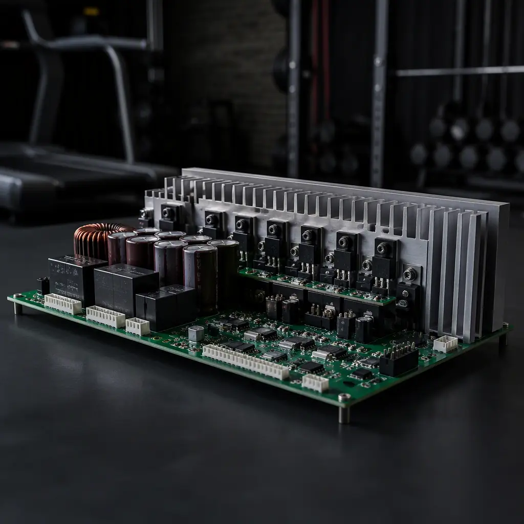
Fitness equipment sits in a category most boards never see: 2-4 HP of continuous motor power, a user standing on the machine, and safety standards (UL 1647 for treadmills, UL 1647/EN 957 for elliptical trainers) that treat a control board failure as a physical hazard. The main drive board must switch 10-20 A through the motor while the console board runs a display, heart-rate sensing and wireless connectivity a meter away. The two boards talk over a cable that carries both power and data. And the EMC picture is dominated by the motor's brushes (or BLDC drive) at full load.
This guide covers the three subsystems in a treadmill or elliptical: the high-current motor drive stage and its thermal design, the safety relay chain that satisfies UL 1647, and the console board with display, heart-rate and connectivity. It closes with the EMC and certification test path. Huaxing PCBA assembles fitness and appliance electronics across 8 SMT lines, the same power-stage rules apply to our home appliance boards and BLDC controller boards.
Motor Drive Stage: Switching 2-4 HP Reliably
Home treadmills use either a brushed DC motor driven by a thyristor (SCR) or TRIAC phase-control stage, or a brushless DC motor with a 3-phase inverter. Commercial machines increasingly use BLDC for efficiency and quieter operation. Both topologies put 10-20 A through the drive board.
Phase-control (SCR) boards: triac cooling and snubber design
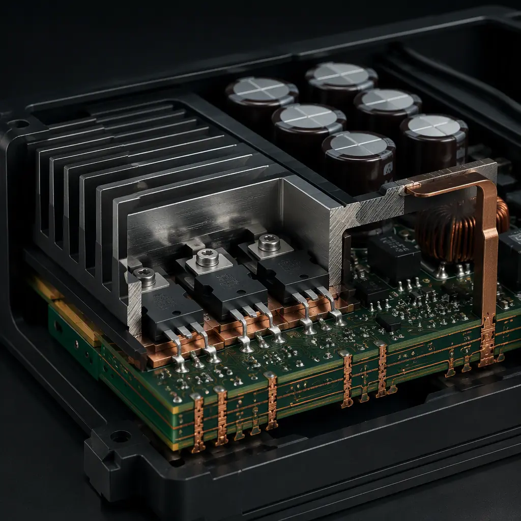
Brushed DC treadmills classically use a TRIAC phase-control stage with a bridge rectifier. The TRIAC and rectifier dissipate 20-40 W at full load and need a substantial heatsink, sized for the worst case of continuous 10 km/h operation at 40 °C ambient. Every TRIAC needs an RC snubber across it to control dV/dt at turn-off; without it, the motor's inductance rings and can re-trigger the TRIAC, producing the classic "motor surges" failure. The layout must keep the snubber leads short and the gate drive away from the power traces.
BLDC boards: inverter sizing and bus capacitance
For a 2 HP BLDC drive at 48-96 V, the inverter MOSFETs must handle 30-50 A peak (start-up and incline surges) with a bus capacitor bank sized for the PWM ripple. The phase outputs and the motor cable need the same common-mode choke treatment as any high-power inverter. The BLDC controller design guide has the full inverter layout rules, and our trace width/current capacity guide covers the copper math for 20 A traces.
Thermal design is the reliability spec
The drive board's lifetime is set by its hottest component. A power stage dissipating 30 W into a board in a partially sealed console area needs a thermal design review: heatsink + forced air or a heat pipe to the chassis. The thermal management guide covers heatsink attachment (screw vs clip), thermal interface material and the board-level copper spreading that keeps MOSFETs below their derated junction temperature.
Key Takeaway: The motor drive stage is a power electronics design, not a digital one. Heatsink sizing, snubbers and bus capacitance decide whether the machine survives a summer of daily use, and they are all PCB decisions.
Safety Chain: UL 1647 and the Relay Logic
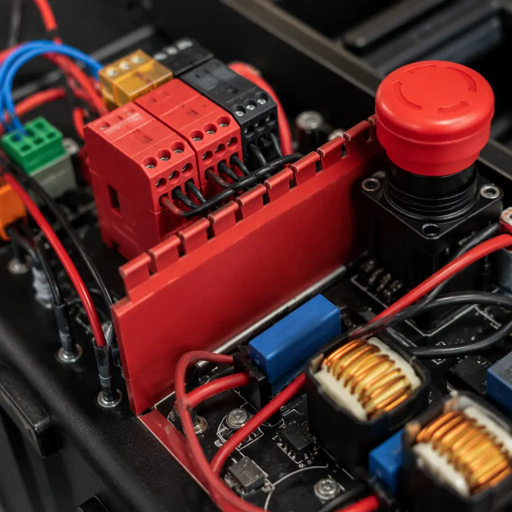
UL 1647 requires that a treadmill stop the belt when the safety key is removed, and that the motor cannot restart without the key. The safety chain is implemented in hardware, a relay (or contactor) in series with the motor power that drops out on any safety condition. Firmware cannot be the only protection.
Safety relay in the motor power path, wired in hardware
The safety key (a magnetic or mechanical key the user clips to their clothing) is wired into the relay coil circuit: key removed = coil de-energized = motor power interrupted. The relay must be a forced-guided (mechanically linked) type for the safety function, rated for the motor's full-load and locked-rotor current, and its contacts must have adequate clearance for the mains/DC voltage. The relay coil is driven by the safety chain, not by firmware, firmware can only request, hardware must enforce.
Independent speed and stop monitoring
UL 1647 also requires that the belt speed follow the commanded speed within limits, and that a failure (e.g., an SCR that sticks on) is detected. This is done with a speed sensor (optical encoder or Hall sensor on the motor/roller) feeding a hardware monitor that compares against the command. If the belt keeps moving after a stop command for more than a defined window (typically 1-2 seconds), the safety relay is dropped. The monitor circuit is separate from the main MCU; two independent paths, per the standard.
Creepage and clearance for the high-voltage sections
The drive board carries mains (or 48-96 V DC) with high-current switching. The PCB must respect the creepage/clearance for the working voltage (typically 6 mm+ creepage for reinforced isolation at 250 VAC), with a clean isolation barrier between the mains section and the low-voltage control section. The high-voltage PCB design guide covers the isolation rules and the slot/v-notch techniques used on appliance boards.
Console Board: Display, Heart Rate and Connectivity
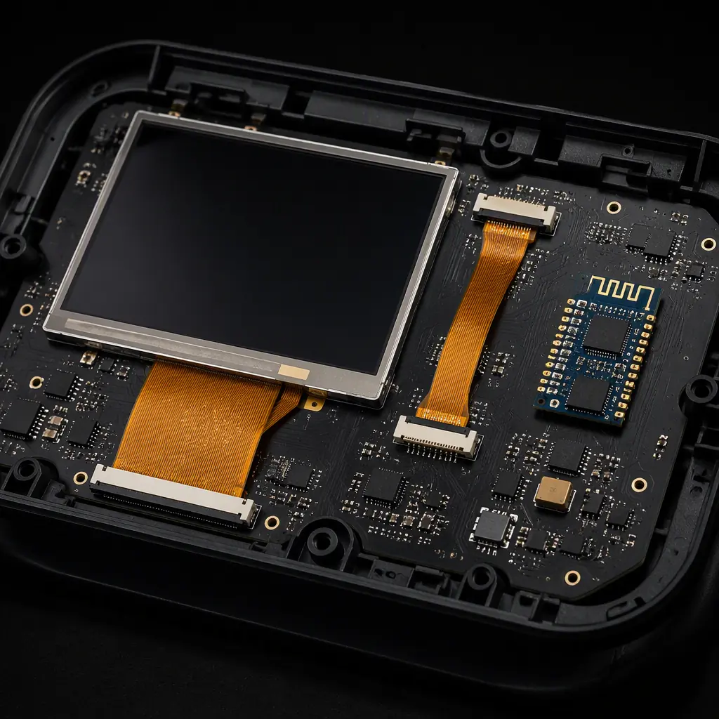
The console is the user interface: a TFT or segment display, capacitive touch keys, heart-rate sensing (chest strap receiver or contact grips), and Bluetooth/Wi-Fi for app connectivity. It is electrically quieter than the drive board but sits in the same cable harness, which is where the noise problems start.
Separate the console ground from the drive ground
The console and drive board connect via a harness carrying power (e.g., 12 V to the console) and signals (speed command, status, heart-rate). The console's ground must be its own island, referenced to the drive board at a single point, so motor current flowing through the harness does not lift the console ground and corrupt the display or the heart-rate analog front end. The harness connector pinout should place ground pins between every signal group (the classic "ground stitching" pinout).
Heart-rate front end: a small analog design
Contact-grip heart-rate sensing reads a few millivolts of ECG through the user's hands, with 50/60 Hz mains coupling as the dominant noise. The analog front end needs a right-leg-drive-style driven shield or a well-filtered differential input, and the trace from the grip contacts to the AFE must be short and guarded. The chest-strap receiver (ANT+/BLE) is a radio design of its own, the BLE PCB guide covers the 2.4 GHz layout.
Display cable and touch controller layout
If the display is a separate panel (common on commercial machines), the LVDS/RGB cable between the console board and the panel is an antenna for motor noise. Use a shielded flat cable or route the display signals differentially with the shield tied to the console ground. The touch controller's I²C bus should stay on the console board, with the sensor traces short and guarded. The display driver board guide covers panel interface layout in detail.
EMC and Certification: The Test Path
Fitness equipment is a motor-driven appliance, which makes it one of the harder EMC classes: a commutating motor is a broadband noise source, and the product must still pass FCC Part 15 / EN 55014 conducted and radiated limits with the motor running at full load.
Input filtering: common-mode choke + X/Y caps
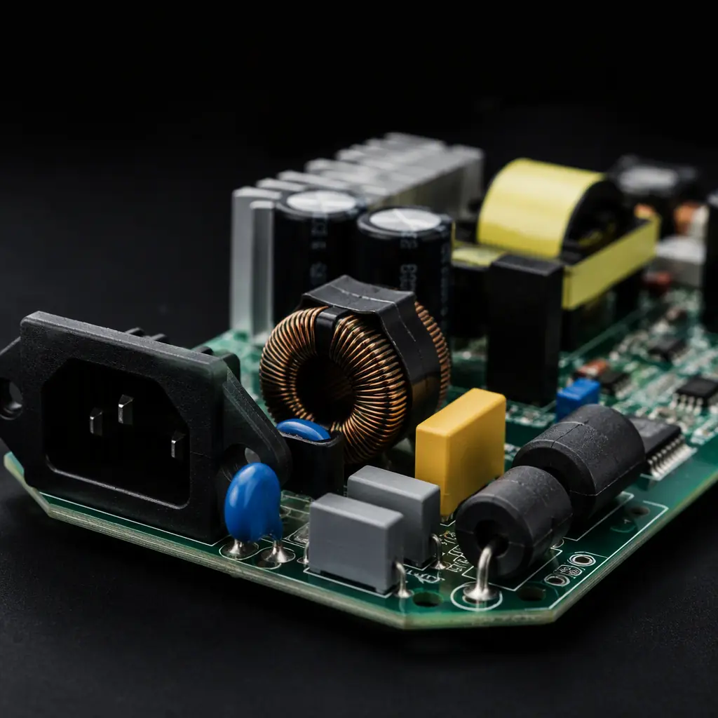
The AC input needs a two-stage EMI filter: a common-mode choke (10-30 mH range for appliance currents) with X-caps across the line and Y-caps to ground. The filter must sit at the power entry, before the rectifier, with the hot and neutral wires twisted and the filter ground tied to the chassis at one point. The layout of the filter section determines whether conducted emissions pass or fail, see our EMC compliance guide for the filter placement rules.
Motor suppression: caps and ferrites at the motor
Brushed motors generate broadband noise at the brushes. Suppression components (0.1 µF caps across the brushes, ferrite beads on the motor leads) belong at the motor or at the drive board's motor connector, the closer to the source, the more effective. The motor cable itself should be shielded or twisted-pair with the shield grounded at the drive board end only (to avoid ground loops).
Test with the real machine, at full load
EMC results on a bench with a resistive load do not predict the machine. The pre-compliance test must run the actual treadmill with the belt loaded (a person or a load roller) at full speed and at incline, measuring conducted on the mains and radiated in the near field. Budget for 2-3 EMC iterations in the project plan, the first layout rarely passes with a brushed motor. The inspection guide covers the production-side verification that follows certification.
Manufacturing and Test for Fitness Electronics
Fitness boards add high-voltage and high-current testing to the standard SMT flow. The production test plan typically includes:
| Test | What It Catches | Where It Runs |
|---|---|---|
| ICT / flying probe | Opens, shorts, wrong values | Post-reflow |
| High-pot (hipot) | Isolation breakdown, creepage defects | Mains section, per unit |
| Safety chain test | Relay drop-out, key removal stop | Functional station, loaded |
| Motor drive test | Phase/SCR firing, speed control, current limit | Load bench or dynamometer |
| Burn-in | Infant mortality in power components | Sampling, powered at load |
Hipot every unit with the safety chain verified
The mains isolation (hipot) test and the safety relay drop-out test are per-unit requirements for a UL-listed product. The hipot tester applies the rated test voltage (typically 1,500 VAC or 2× working voltage + 1,000 V) between the mains section and the exposed metal parts, and the test log is part of the certification record. The testing methods guide covers the station design and the pass criteria.
Load-test the drive stage, not just power it
A drive board that passes a no-load power-on test can still fail at full belt load. The production functional station should load the motor (a load roller or a loaded belt) and verify speed accuracy, current limiting and the thermal protection trip. Sampling at full load is acceptable for thermal (burn-in), but the electrical load test should run on a higher percentage of units.
Conformal coating for the console, moisture protection for the drive
Fitness equipment lives in humid environments (homes, gyms) with sweat and cleaning chemicals. The console board should get a thin acrylic conformal coating, and the drive board's low-voltage section should be coated while the power section stays bare for heatsink contact. The conformal coating guide covers the material and masking choices for mixed power/control boards.
Building Fitness Equipment That Survives Daily Use
The design order for a treadmill or elliptical is: the motor drive and its thermal design first, then the hardware safety chain (relay + independent monitor) that the standard demands, then the console with its ground isolation and heart-rate front end, and finally the EMC filter and suppression that make it certifiable. Each is a board-level decision, heatsink area, relay ratings, isolation barrier, filter placement. Verify hipot and the safety chain on every unit, load-test the drive on a meaningful sample, and coat for the humidity the machine will actually live in. The machines that run for years in commercial gyms are the ones whose boards were treated as power electronics with a safety function, not as another digital product.
Huaxing PCBA assembles fitness and appliance control boards with hipot-tested mains isolation, load-tested drive stages and conformal coating across 8 SMT lines. Read our appliance PCB guide for the high-voltage rules, or send your BOM and motor specs . We'll return a DFM review covering heatsink design, the safety chain and EMC filter layout with your quote within 24 hours.
