
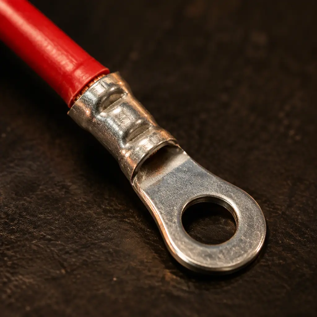
Every wire harness that leaves a factory carries hundreds of crimped connections, and almost all of them are electrically fine on the day they are made. The failure that matters is the marginal crimp: one where the barrel did not fully compress the strands, or where the wire was inserted to the wrong depth, or where a strand was nicked by the die. That joint passes a simple continuity buzz in the factory and fails months later when vibration or thermal cycling works the imperfection open.
The remedy is not more inspection of the finished harness. It is specifying three acceptance tests — pull force, micro-ohm resistance, and continuity combined with a withstand test — in the right places in the build, so a bad crimp is caught at the crimp station rather than at the customer. This is the same logic that makes any design-for-assembly program pay off: catch the defect where fixing it is cheap.
Why Crimps Fail
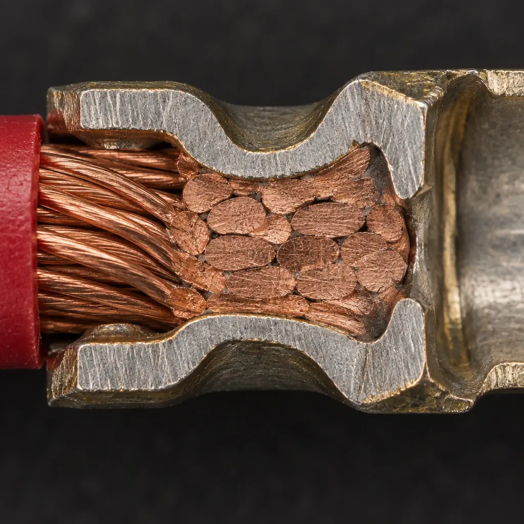
A correct crimp works because the terminal barrel is compressed until the copper strands and the barrel wall cold-weld into a single conductive mass. The failure modes all attack that weld, and each has a distinct signature that testing can catch.
- Cold crimp. The press delivered insufficient force, so the strands are compressed but not welded. Signature: resistance creeps upward under thermal cycling; pull force is low but not always obviously low.
- Over-crimp. Excessive force crushes the strands, reducing the conductor cross-section and notching the barrel. Signature: reduced current capacity and a brittle joint that cracks under flexing.
- Wrong die or wrong terminal for the wire gauge. The barrel geometry does not match the conductor, so the weld never forms properly. Signature: pull force falls below the gauge-specific minimum.
- Insulation in the barrel. Wire insulation was inserted into the crimp zone instead of only the strain-relief zone. Signature: high resistance and a joint that pulls out at very low force.
- Strand nicking. The stripping tool cut into the conductor. Signature: intact crimp but a wire that breaks in the stripped region under vibration.
Crimp Pull-Force Acceptance
Pull force is the primary acceptance test for a crimp, and it is destructive — you pull a sample to failure and record the peak force. The minimum value scales with wire gauge, because a thicker conductor has more material to weld. The values below are typical minimums drawn from common harness-acceptance practice; the exact figures should be taken from the applicable standard for your program.
| Wire Gauge (AWG) | Typical Min. Pull | Test Frequency |
|---|---|---|
| 26–24 | 20 N | first article + sample |
| 22–20 | 40 N | first article + sample |
| 18–16 | 80 N | first article + sample |
| 14–12 | 140 N | first article + sample |
| 10–8 | 220 N | first article + sample |
Pull testing is destructive, so it cannot be run on every joint. The workable strategy is a first-article pull test that sets the process, followed by periodic sampling tied to the crimp tool's maintenance cycle. If the press has a force monitor, that monitor is the in-process control and the destructive sample is the periodic proof — the same relationship a process-control chart has to a capability study in PCBA.
Micro-Ohm and Voltage-Drop Limits
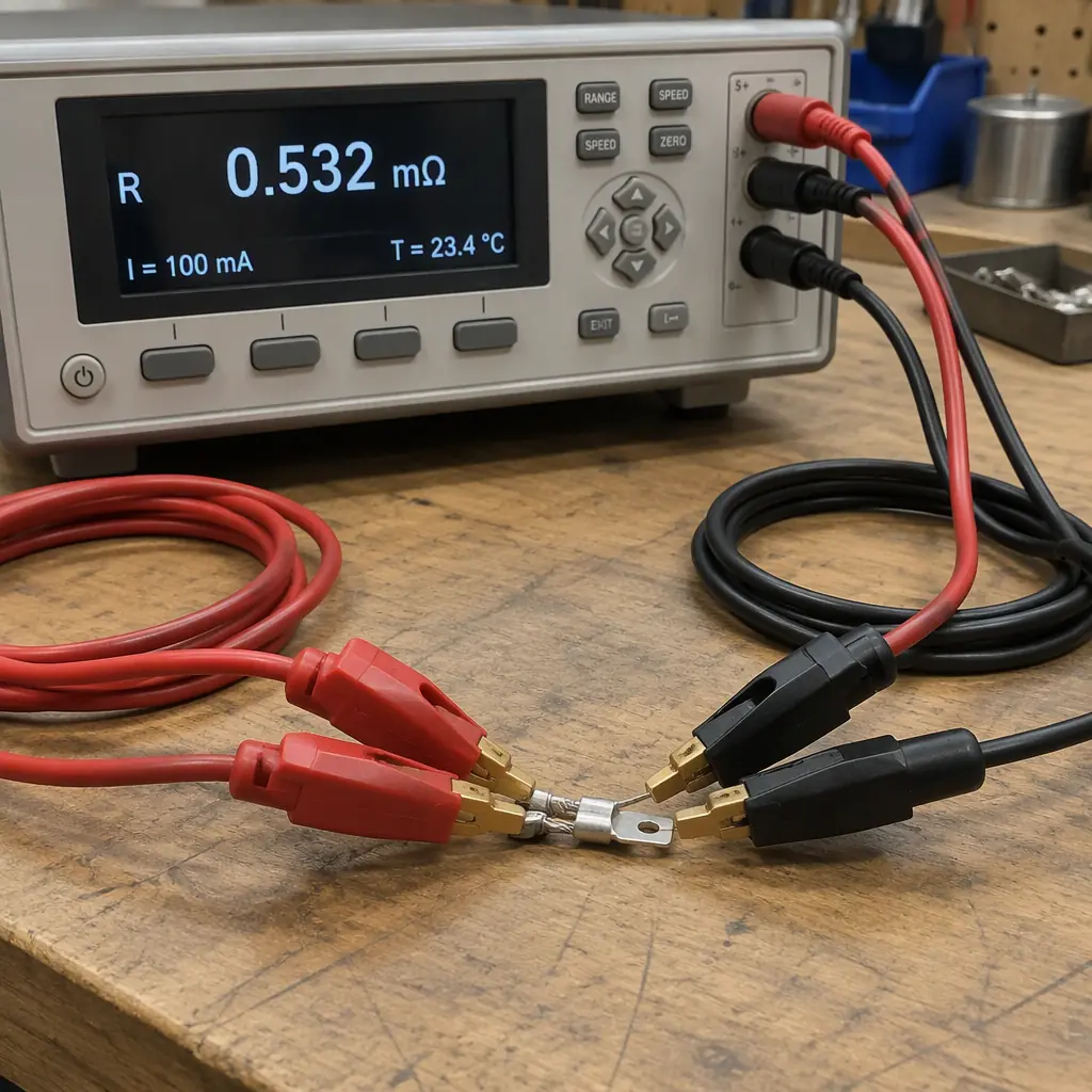
Resistance testing is the non-destructive complement to pull force. A good crimp adds almost nothing to the resistance of the wire it joins; a marginal crimp adds measurably more, and the added resistance is what turns into heat under load. Measuring it requires a four-wire (Kelvin) milliohm meter, because a two-wire meter's lead resistance swamps the value you are trying to read.
The acceptance rule that works in practice is not a single absolute number but a comparison: the resistance of the crimped joint is measured against the resistance of an equal length of the same wire, and the difference — the crimp's contribution — is held to a defined ceiling. A commonly used, defensible limit is that a crimp should contribute no more than a few milliohms, with the exact ceiling scaled to the conductor. Expressed as a voltage drop at rated current, the same requirement becomes easier to inspect on the line: measure the drop across the joint at a defined test current and compare it to the limit in the harness specification.
Continuity and Hi-Pot / Withstand Testing
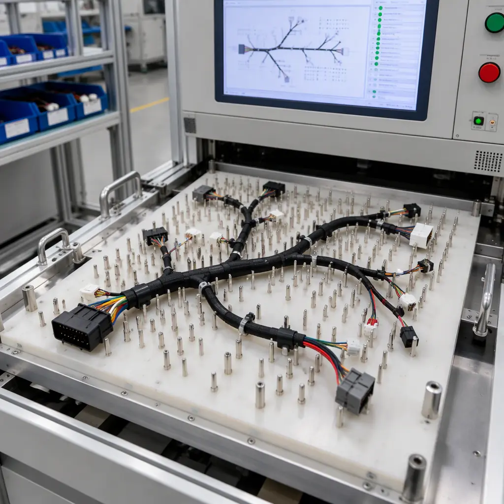
Continuity testing verifies that the harness is wired to the right pinout — every conductor lands where the drawing says it should, and no unintended connection exists between circuits. On a multi-branch harness this is best done with an automated continuity tester that learns the correct netlist and flags any deviation, including a short between adjacent conductors that a simple buzz test would miss.
Where the harness carries mains or high-voltage circuits, a dielectric withstand (hi-pot) test applies a specified voltage between conductors and between conductors and ground for a defined period, and confirms no breakdown occurs. The test voltage and duration come from the safety standard governing the end product; they are not a free choice. Setting the hipot test correctly at first article, and running a shortened in-process version on every unit, is what turns a safety requirement into a repeatable gate rather than a checkbox.
- Continuity: 100% of units, against the drawing netlist, using an automated tester.
- Resistance: sample, with a Kelvin meter, on crimps across the gauge range used.
- Hi-pot: 100% of units for high-voltage harnesses, at the standard's voltage and duration.
- Pull force: destructive sample per tool-maintenance cycle and at first article.
Building the Test Plan into the Build
A test plan that is written after the harness is built is a quality report; a test plan that is written into the routing is a control. Three placements make the difference:
- At the crimp station. If the press has force or crimp-height monitoring, that is the in-process check. Pair it with a documented pull-test schedule so the monitor's calibration is verified.
- At sub-assembly. Test each branch before it is bundled into the main harness. A fault found in a loose branch is a one-minute fix; the same fault found in a bundled harness is a de-loom and rework.
- At final assembly. Full continuity and, where required, hi-pot on the completed unit, against the released drawing.
The documentation that accompanies the harness matters as much as the tests. A report that lists the tests run, the values measured, the serial or lot, and the date gives the buyer traceability that a simple pass stamp does not. Where the harness is part of a larger box-build, this becomes part of the same evidence package as the board-level tests — the discipline of box-build value-add is that every purchased and assembled element carries its own proof.
Specifying Wire, Terminals and Test on the Drawing
The drawing that removes ambiguity names the wire gauge and insulation type, the terminal part number and the correct tooling, the strip length, the insertion depth, and the acceptance tests with their values and frequencies. If the harness mates to a board through a press-fit or a soldered connector, the connector interface belongs on the same drawing so the mechanical and electrical requirements are stated once. The concerns that drive press-fit technology — contact retention and interface integrity — are the connector-side analogue of a good crimp, and the two are usually specified together.
Costing a harness without stating the test plan produces a quote that assumes the least testing. Stating the plan up front, with the frequencies above, produces a quote that reflects what the program actually needs and a harness that fails in the factory rather than in the field. Assembly cost is far cheaper to correct at quote stage than after a warranty event.
At Huaxing PCBA harness and cable work is quoted as a box-build value-add, with the crimp tooling, pull-force sample schedule and continuity netlist agreed at the front end. We build and test to the released drawing, run automated continuity on 100% of units, and hold crimp pull force to the gauge-specific minimum across AWG 26 through 8. Send your harness drawing and test requirements for a quote or talk to an engineer about your cable assembly program.
