
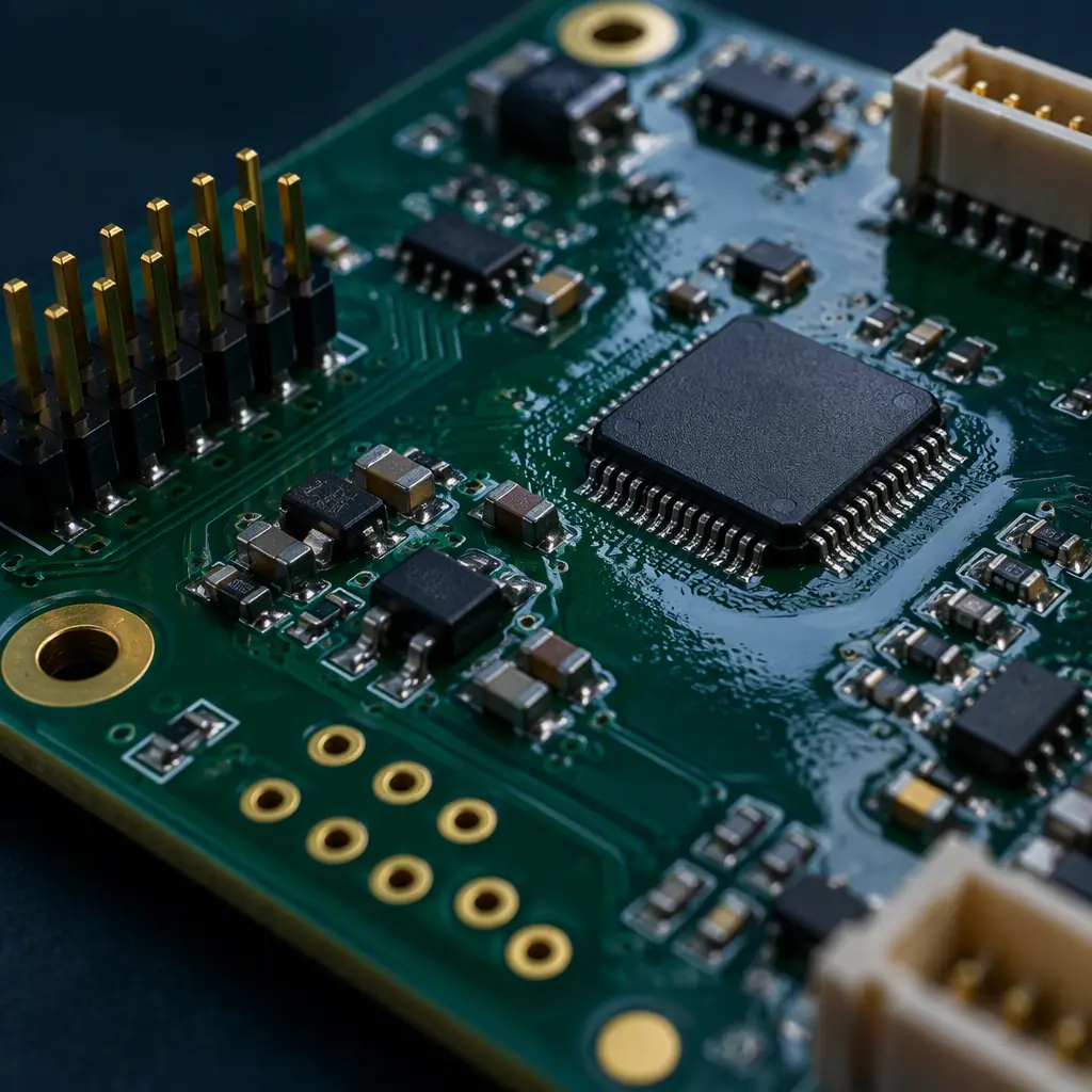
A conformal coating line only does its job if it coats the right areas and leaves the rest bare. Every connector cavity, test pad, press-fit hole, card-edge finger, mating surface and optical window has to stay free of coating — not because the coating would fail there, but because a coated connector cannot be mated reliably, a coated test pad cannot be probed, and a coated press-fit hole cannot accept a compliant pin without damaging the plating. Masking is the operation that creates that boundary.
It is also where cost and risk concentrate. Masking is manual on most lines, it scales with the number of keep-out features rather than board area, and the consequences of a missed keep-out are asymmetric: over-coating a decorative area is invisible, while over-coating a connector means either a rework operation on a finished assembly or a scrapped board. At Huaxing PCBA we run coating on 8 SMT lines with dedicated masking stations for medical, automotive and aerospace programs, and the masking decision is one of the first things we align with a customer before the first article is coated.
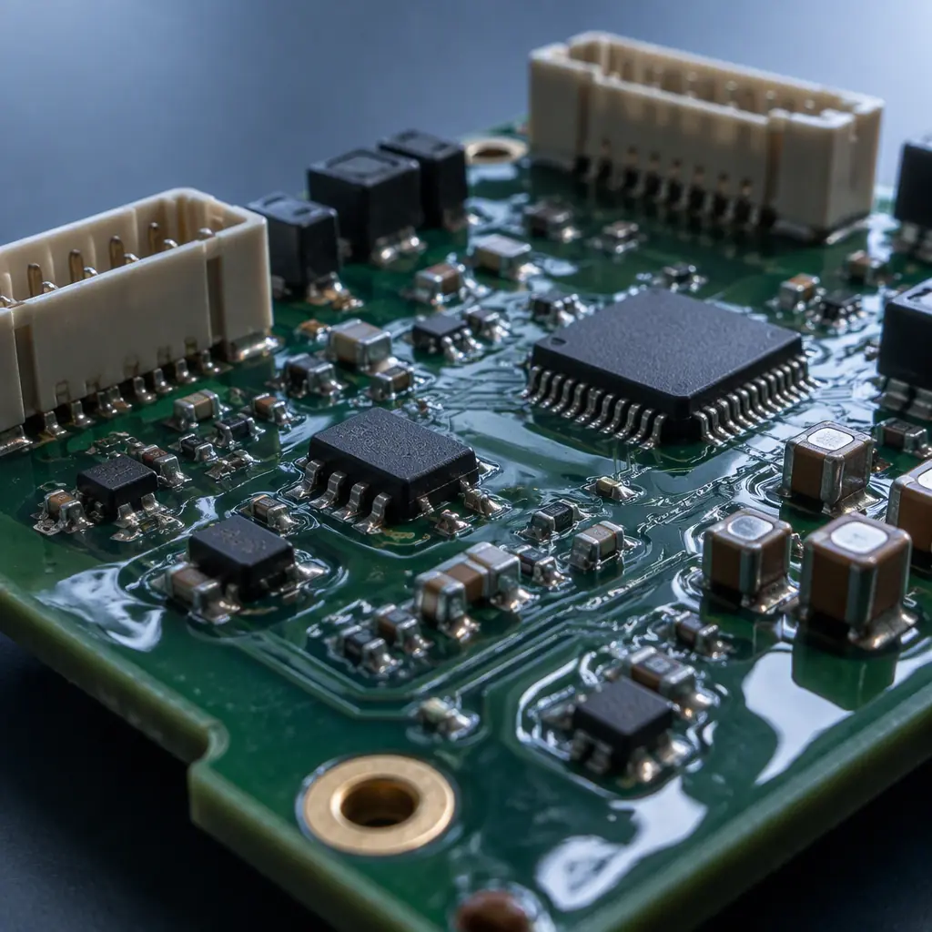
The Cost of Getting Masking Wrong
Masking failures are not subtle. They fall into three buckets, and each has a different recovery cost. Understanding which bucket a design is exposed to is the first step in choosing a masking method, because the method should be selected against the failure mode it prevents.
Coated Connectors — Typically Rework or Scrap
A connector body that picks up a film of acrylic or urethane coating will not seat properly. The coating film, typically 25 to 75 micrometres thick, changes the insertion geometry and can prevent the latch or the contact wipe from engaging. If the coating is a solvent-removable acrylic or urethane, it can often be stripped locally with a solvent and a swab — but only if the connector is not a fine-pitch ZIF or board-to-board part where solvent wicks into the contact area. On a high-value assembly, a coated fine-pitch connector is usually a scrap event. This is the failure mode that justifies spending real money on masking.
Coated Test Points — Untestable Board
Test pads and diagnostic vias must remain electrically accessible for functional test, bench debug and field service. Coating over a test pad is rarely catastrophic — a pogo pin will usually penetrate a soft acrylic or silicone film — but a hard, fully cured epoxy or parylene film will blunt the pin or simply insulate the pad. On boards that go through in-circuit test after coating, or that carry a field-service requirement, masking test points is not optional. It is usually the single largest contributor to the number of masked features on a board.
Coated Grounding and Shielding Surfaces — Intermittent Contacts
EMI gaskets, chassis ground pads, screw-down grounding bosses and shield can lands rely on direct metal-to-metal contact. A coating film under a gasket creates a high-resistance or intermittent ground that passes continuity test at low current but degrades under vibration or thermal cycling in the field. This is the most expensive failure mode because it typically escapes both visual inspection and electrical test and appears as a customer field failure. Masking requirements for grounding surfaces must be flagged explicitly on the drawing, not left to the coater's judgement.
Key Takeaway: Masking is specified against failure consequences, not board area. A board with one fine-pitch board-to-board connector and no test points needs more careful masking than a board with fifty test pads and no connectors.
The Four Masking Methods a Fab Actually Uses
There are exactly four ways a production coating line keeps coating off a feature, and in practice most boards use a combination of two or three. The method is chosen per feature type, not per board, because a connector cavity and a flat ground pad present completely different masking problems.
| Method | Best For | Precision | Labour Intensity | Residue Risk | Reusable |
|---|---|---|---|---|---|
| Polyester / silicone tape | Flat pads, card-edge fingers, large keep-outs | ±0.5 mm | High | Low — adhesive can leave residue | No |
| Peelable liquid mask | Irregular shapes, large areas, high feature count | ±0.3 mm | Medium | Medium — must fully cure | No |
| Silicone boots, caps, plugs | Connector cavities, through-holes, threaded inserts | ±0.2 mm | Low per unit at volume | Very low | Yes, 20–50 cycles |
| Automated selective dispense (no mask) | High-volume, stable layouts, flat boards | ±0.1 mm | Very low | None | N/A |
Polyester and Silicone Tape — The Default for Flat Keep-Outs
Pressure-sensitive tape is the oldest and still the most common method. Polyester tape with a silicone adhesive is the standard choice because it conforms well to flat surfaces, releases cleanly after thermal cure, and tolerates the 80 to 130 °C cure cycles typical of conformal coating without embrittling. Kapton (polyimide) tape is used where cure temperatures exceed 150 °C or where the board will also see a reflow-adjacent thermal excursion. Tape is fastest to apply on large flat areas such as card-edge gold fingers, and it is the cheapest material per square centimetre. The limitation is precision: tape cannot follow a 0.5 mm-pitch pin field accurately, and every taped feature is a manual operation.
Peelable Liquid Mask — Precision on Irregular Geometry
Peelable mask is a thixotropic latex or silicone-based compound applied by hand dispenser, stencil or screen print, cured to a rubbery film, and peeled away after coating. Its advantage is geometry: it will fill a connector cavity, wrap a chamfered edge or cover an irregular ground plane that tape cannot reach. It is also the only method that scales reasonably to boards with very high keep-out feature counts, because application can be automated with a dispense robot. The risk is residue — if the mask is under-cured, it smears during coating and tears on removal, leaving fragments on the board that show up later as solderability or ionic cleanliness failures. Peelable mask cure schedules must be followed exactly; a shortened cure is a false economy that surfaces at test.
Silicone Boots, Caps and Plugs — The Volume Answer for Connectors
Silicone masking boots are moulded to a specific connector or hole geometry and push into place in a second or two. A typical connector boot costs five to twenty times a tape solution per feature, but if the board runs at volume the boot is reusable for 20 to 50 coating cycles, which brings the amortised cost below tape — and it does it with far better repeatability, because the boot physically cannot be placed half-on. Boots are the standard answer for D-sub and Micro-D connectors, RJ45 jacks, board-to-board headers, USB receptacles, threaded inserts and press-fit holes that must stay clear. The trade-off is lead time: a boot is a custom moulded part, so a new connector requires a new tool.
Automated Selective Dispense — Eliminating the Mask Entirely
A programmable selective coating robot applies material only where it is told, following a teach file derived from the CAD keep-out geometry. For a high-volume product with a stable layout, this outperforms every masking method: no consumable, no manual operation, no residue, and placement accuracy around ±0.1 mm — tighter than any manual technique. The constraints are that the robot needs a flat, rigid board to maintain standoff, the dispense pattern must be re-taught for every layout change, and it is a poor fit for low volume or a high mix of part numbers. Many lines, including ours, use selective dispense for the majority of coating area and retain boots or tape for the small number of features the nozzle cannot safely avoid. Our guide to conformal coating covers how the coating itself is selected; this article covers the boundary.
Matching the Method to the Coating Chemistry
Masking method and coating chemistry are not independent choices, because the solvent system of the coating attacks the masking material. Selecting masking without reference to chemistry is the most common specification error we see, and it produces failures that look like masking defects but are actually compatibility defects.
| Coating | Solvent System | Recommended Masking | Critical Constraint |
|---|---|---|---|
| Acrylic (AR) | Solvent, often xylene or toluene based | Any method; peelable mask performs well | Solvent dissolves uncured peelable mask — full cure mandatory |
| Polyurethane (UR) | Solvent or solvent-free | Polyester/Kapton tape or silicone boots | Strong adhesion; poor wetting of silicone masks can cause wicking under edges |
| Silicone (SR) | Solvent, moisture-cure or addition-cure | Silicone boots; avoid silicone peelable mask | Coating and mask chemically similar — release may be incomplete |
| Parylene (XY) | Vapour deposition, no solvent | Boots, caps and plugs only | Vapour penetrates every gap; tape shadowing is unreliable |
| UV-cure acrylic | Solvent-free, cures by UV | Any method; opaque masks shade the keep-out | Ensure enough UV dose reaches coating not shielded by mask |
Key Takeaway: Parylene is the outlier. Because it deposits from a vapour phase at low pressure, it reaches surfaces that tape cannot shadow, and masking reliability depends on mechanical sealing rather than adhesion. Parylene masking almost always means moulded boots, caps or plugs — never tape.
Parylene deserves its own treatment because the deposition mechanism changes the masking problem fundamentally. A solvent-borne coating needs the mask to create a liquid-tight adhesive seal at the feature boundary. Parylene needs the mask to create a vapour-tight mechanical seal, because the monomer gas will migrate along any unbonded interface. Practical parylene masking uses moulded silicone caps and plugs inserted with light compression, frequently with a secondary silicone gel at the seam. Because of this, our parylene coating guide treats masking as a first-class process step, and our article on coating types compared explains when parylene's masking overhead is still worth the performance gain.
Fine-Pitch, Connectors and the Keep-Out You Cannot Tape
The hardest masking problems are not large — they are small and dense. A 0.4 mm pitch board-to-board connector, a fine-pitch FPC ZIF, a press-fit backplane hole field and a 01005-populated test pad array all fall into the same category: the keep-out features are too small and too close together for tape, and they are fragile enough that a solvent wipe cannot be used as a fallback.
For these features the only reliable answers are moulded boots or an engineered peelable that is dispensed rather than placed. When evaluating a quote for a board with fine-pitch keep-outs, ask the supplier directly which of the two they intend to use and how they will verify it. A supplier who answers "we tape it" for a 0.4 mm pitch connector is telling you they have not thought about the problem.
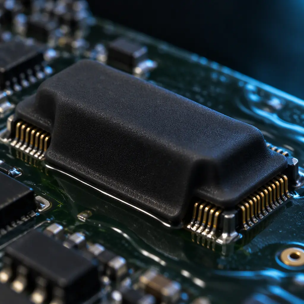
Two design decisions reduce masking difficulty before the board is ever built, and both are worth raising at DFM review. First, cluster keep-out features where possible: a single test pad cluster at one board edge needs one masking operation, while the same pads distributed across the board need eight. Second, prefer connectors that have a commercially available moulding boot over connectors that do not. The connector chosen at design stage determines whether masking at volume is a two-second operation or a thirty-second manual task, and over a production run that difference is significant.
Masking Residue, Cleanliness and IPC-CC-830
The interaction between masking and board cleanliness is the most under-specified part of the coating process, and it is where masking defects show up as electrical failures rather than cosmetic ones. IPC-CC-830 defines qualification and performance requirements for conformal coating materials, and J-STD-001 sets the cleanliness and process requirements that apply before coating is applied. The relevant point is that masking residue is a contamination source.
Adhesive residue from tape, uncured peelable mask fragments, and silicone transfer from a worn boot all leave organic and ionic material on surfaces that may then be coated over. Under the coating, that residue is trapped. On a high-impedance or high-voltage node, trapped ionic contamination combined with humidity produces electrochemical migration — dendrite growth between adjacent conductors that presents as a leakage failure weeks or months into service. This is a slow failure that escapes production test entirely.
The controls that prevent it are straightforward but must be explicit in the process specification. Masking materials should be qualified for the coating chemistry rather than selected on price. Tape adhesive systems should be silicone-based for high-reliability work, because acrylic adhesives leave more residue. Peelable mask cure should be verified, not assumed. And cleanliness verification should follow coating, not precede it — our article on ionic contamination and cleanliness testing covers the test methods, and our breakdown of aqueous versus solvent cleaning explains why the cleaning step interacts with mask residue. Buyers specifying coating for medical, automotive or aerospace programs should require an ionic cleanliness result on coated boards, not just bare boards.
Where the board will be potted or encapsulated rather than coated, the masking picture changes again — a potting compound can be contained by a dam rather than a mask, and the keep-out is defined by an enclosure. Our potting and encapsulation guide covers that route, and the IPC-A-610 coating acceptance criteria article covers how a coated board is judged once masking is removed.
Cost and Throughput per Method
Masking cost is driven by the number of keep-out features and the labour model, not by board area. The figures below are representative for a 100 mm × 100 mm board with a moderate keep-out count, and they are the numbers we use when advising a customer on method selection. They exclude coating itself.
| Method | Application Time per Feature | Removal Time per Feature | Consumable Cost | Practical Volume Band |
|---|---|---|---|---|
| Polyester tape | 8–20 s | 5–10 s | Very low | Prototype to 500 units |
| Peelable liquid mask | 4–12 s (hand) / 1–3 s (dispensed) | 3–8 s | Low | Prototype to 5,000 units |
| Silicone boots / caps | 1–3 s | 1–2 s | High first article, low amortised | 500 units upward |
| Automated selective dispense | 0 s (programmed) | 0 s | Programme cost only | 2,000 units upward, stable layout |
The crossover pattern is consistent. Tape wins on prototypes and low volume because there is no tooling cost. Peelable mask wins in the middle because it handles complex geometry without tooling. Boots win at volume because the reusable part amortises the moulding cost quickly and the per-unit labour collapses. Automated dispense wins at high volume with a stable layout because it removes the operation entirely. A supplier who pushes one method for every programme is optimising for their own convenience rather than for your cost.
Procurement Note: Ask for masking to be quoted as a separate line item with the method named. A single blended "coating service" price hides which method is being used and makes it impossible to compare suppliers on a like-for-like basis.
Summary and Next Steps
Masking determines whether a conformal coating programme succeeds or turns into a rework exercise. The method should be chosen per feature type and validated against the coating chemistry — tape for flat keep-outs, peelable mask for irregular geometry, moulded boots for connectors and holes at volume, and automated dispense to remove the operation entirely where the layout is stable. Residue control and post-coating cleanliness verification are what separate a coating that survives field service from one that fails months later as an intermittent ground or a leakage path.
At Huaxing PCBA we coat boards on dedicated lines with masking stations for medical, automotive and aerospace programmes, and we treat masking method selection as part of DFM review rather than a downstream process detail. We stock moulded boots for common connector families, run selective dispense for high-volume layouts, and verify ionic cleanliness after coating on request. Send your Gerber and BOM with the keep-out features marked, and our engineering team will come back within 24 hours with a coating and masking recommendation, a DFM review and a quote. You can also read our full conformal coating guide or contact our engineering team to discuss a specific assembly.
