
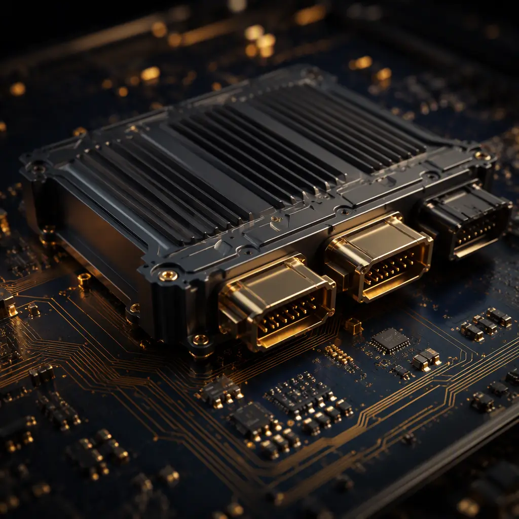
The traditional vehicle wiring architecture assigns one electronic control unit (ECU) to each function, body, powertrain, lighting, doors, seats. A modern car can hold over 100 ECUs and kilometers of wiring. Zonal architecture flips that model: instead of an ECU per function, the car is divided into physical zones (front, rear, left, right), and each zone gets a single zonal gateway that fans out to the sensors and actuators physically near it. One central compute node runs the software that used to be spread across dozens of boxes.
The payoff is dramatic: less copper, less harness weight, faster OTA updates, and the ability to centralize the intelligence in a modern high-power compute board. Which is exactly the kind of board Huaxing PCBA builds on 8 SMT lines up to 32 layers.
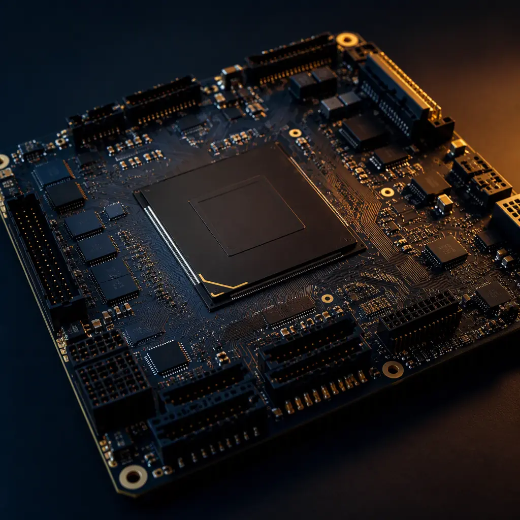
Zonal vs Domain, What Changed in the Electrical Architecture
To specify the board correctly, you have to keep the two architectures straight, because they impose different connectors, different Ethernets, and different safety partitioning.
Domain Architecture (What You Are Replacing)
Domain architecture groups ECUs by function: a powertrain domain, a chassis domain, an infotainment domain, a body domain. Each domain has its own controller, and domains talk over a backbone like CAN or a 100M Ethernet. The drawback is the number of ECUs and the harness complexity to feed each one.
Zonal Architecture (What You Are Building Toward)
Zonal architecture groups by physical location. A front zonal gateway handles every sensor, actuator, and switch in the front zone; a rear gateway handles the rear. They all connect back to a central compute node over a high-speed, redundant Ethernet ring. See our automotive Ethernet design guide for how that layer-1 topology is built.
Why It Drives the PCB
Fewer, bigger boards replace many small ones. The central compute node becomes a dense, high-layer, high-speed board. The zonal gateways become robust, everything-in-one boards that route a mix of power, high-speed data, and sensor I/O. The design centers on the harness savings, which is exactly what makes it attractive to OEMs.
The Central Compute Node, The Pinch Point
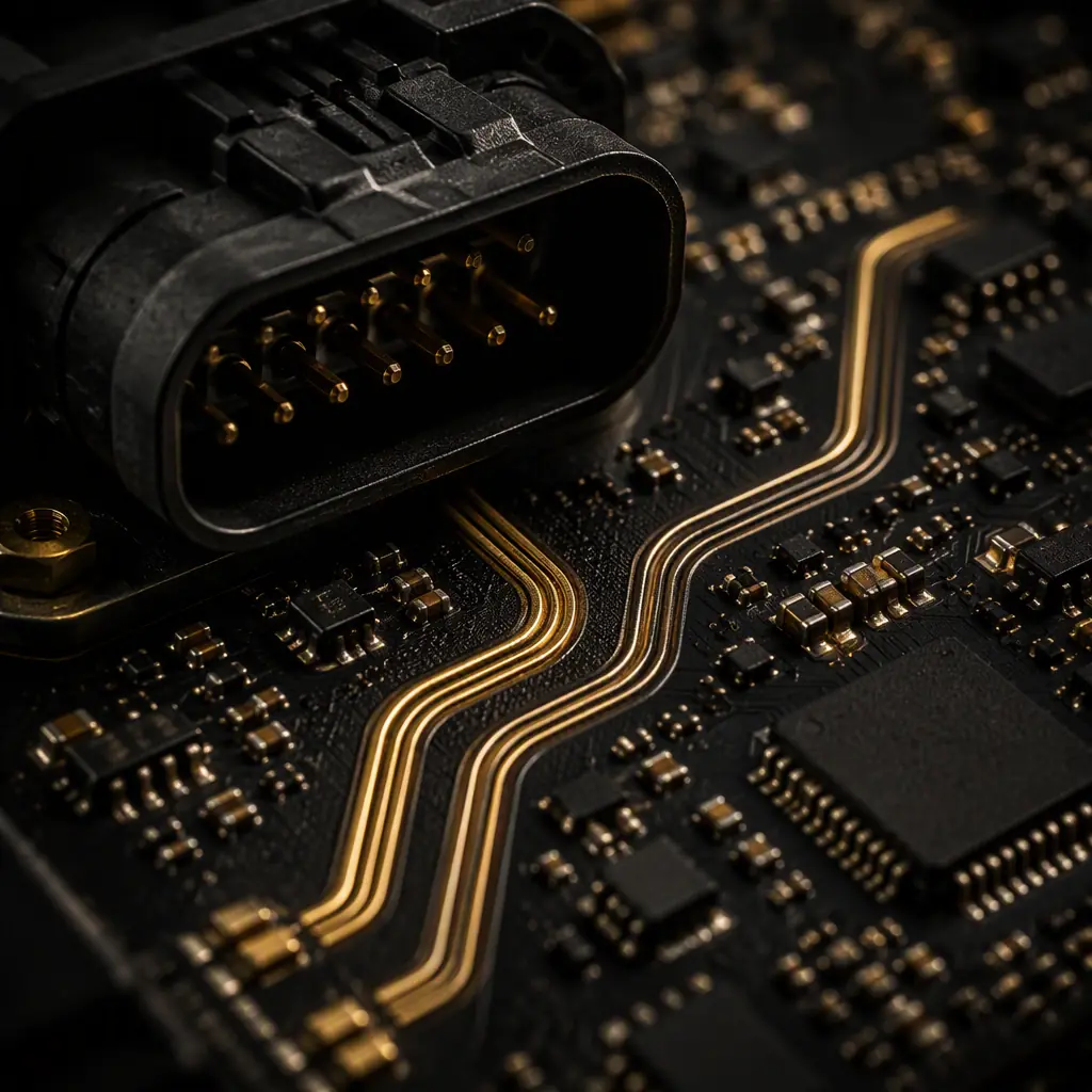
The central compute node (often called the central compute unit or high-performance compute) hosts the autonomous driving and infotainment stack. Its board is the most demanding automotive PCB to manufacture.
High Layer Count for Compute
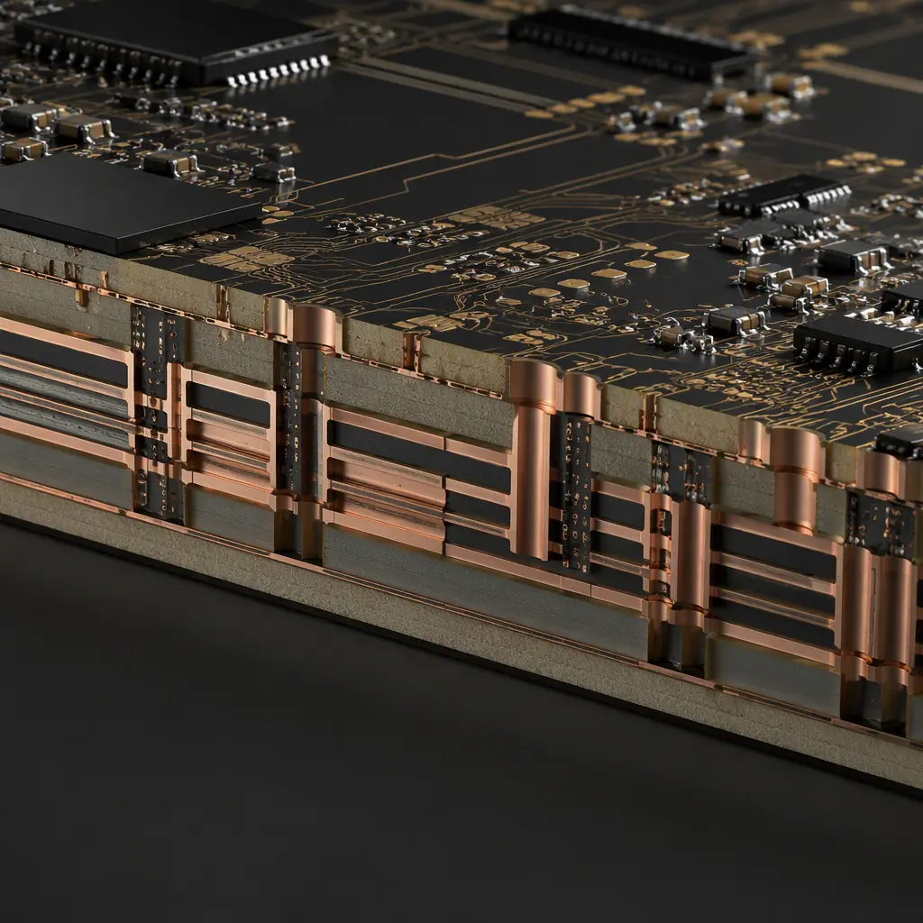
The compute node fans out a large SoC, high-bandwidth memory, and dozens of high-speed lanes. That routinely means 16-32 layers with careful stackup. See our layer count selection guide and our stackup design guide.
High-Speed SerDes and Memory
The compute node runs 10G+ Ethernet, PCIe and high-speed memory interfaces. The design rules for these are no different in principle from a data-center board, but they have to survive automotive thermals. See our PCIe design guide and our signal integrity guide.
Thermal Management Under the Hood
The compute node dissipates 50 W or more in a sealed, hot environment. Efficient thermal design and heavy copper for current paths matter. See our thermal management guide for the approach.
| Attribute | Typical Zonal Requirement | Design Note |
|---|---|---|
| Automotive Ethernet | 100BASE-T1 to 10GBASE-T1 | 1 pair, shielded, low loss |
| Central compute layer count | 16 – 32 | Dense SoC and memory fan-out |
| Zonal power domain | 12/24/48 V | Drive fuses, nets, and heavy copper |
| Functional safety | ASIL B – D | Drives fault-tolerant layout and redundancy |
| Min line / space | 3/3 mil | Fine-pitch BGA and breakout |
Safety, Power and the Interface to the Real World
The zonal gateway is the physical I/O hub of the vehicle zone. It has to switch current to motors and actuators, carry data from sensors, and do it all under ASIL-rated failure requirements.
Functional Safety at the Board Level
Zonal architecture concentrate safety-critical functions into fewer boards. That raises the ASIL requirement on each board. Layout decisions, redundant paths, separation of safety and non-safety domains, single-point fault detection, are all part of the design. See our ISO 26262 functional safety guide and our IEC 61508 guide.
Power Domains and Fusing
A zonal gateway switches several power rails, 12 V body, 24 V commercial, or 48 V mild-hybrid, to local loads. Fusing, reverse-polarity protection, and current-monitoring are mandatory. The board handles real current, so copper weight and trace sizing are critical. See our trace width and capacity guide for sizing.
EMC in a Noisy Vehicle
Automotive electronics live next to ignition, motors and dozens of switched loads. The gateway must withstand and emit little electromagnetic noise. Many OEMs refer to CISPR 25 for emissions and immunity, see our CISPR 25 guide and our EMI/EMC design guide.
Manufacturing Quality for Automotive Production
Automotive boards have no tolerance for field failures. The manufacturing and quality processes are as important as the design.
IATF 16949 and PPAP Readiness
Automotive production boards need an IATF 16949 quality system and, for new parts, PPAP. Huaxing PCBA is certified to IATF 16949 and ISO 9001 and supports PPAP documentation. See our PPAP guide and our certifications guide.
Inspection and Reliability Testing
Automotive boards need full AOI, X-ray and, for safety parts, extended reliability testing like thermal cycling and vibration. See our testing methods guide, thermal cycling guide, and vibration and shock testing guide.
Conformal Coating and Protection
Automotive electronics face condensation, salt and vibration. A conformal coating protects the board, but it must be applied correctly around connectors and high-current domains. See our conformal coating guide.
Summary, Building the Zonal Board
A zonal architecture board is a synthesis of a dense compute node, a rugged I/O gateway, and a safety-critical control board. At the compute node, push to 16-32 layers with careful high-speed routing and thermal management. At the gateway, isolate the safety, data and power domains, switch real current with adequate copper, and test hard. Then build it under IATF 16949 with PPAP and full reliability validation.
At Huaxing PCBA we build 2-32 layer automotive boards on 8 SMT lines with IATF 16949 and ISO 9001 certified quality, supporting IPC Class 2/3 acceptance and PPAP. We offer a free DFM review on the safety partitioning, Ethernet routing and power layout of your zonal gateway or central compute node, so it releases reliably. Send your files for a quote or talk to an engineer about your vehicle E/E board.
